

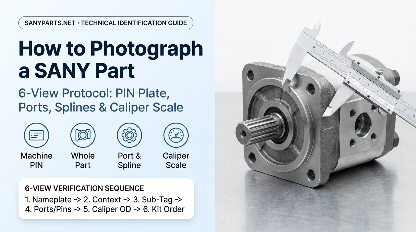
Submitting a single angled smartphone photo or an unverified raw casting mark causes wrong-part shipments, hydraulic port thread mismatches, and days of avoidable excavator or crane standby downtime. To photograph a SANY part for identification accurately, capture a fixed six-view engineering sequence combining the 17-character ISO 10261 machine PIN plate, orthogonal full-part context views, the component sub-vendor data tag, straight-on connector pinouts or hydraulic flange ports, and coplanar vernier caliper measurements.
Engineering identification summary: When sourcing replacement parts for SANY excavators, cranes, concrete pumps, or reach stackers without a confirmed factory parts book, visual appearance alone cannot distinguish mid-series production breaks, internal valve calibrations, or metric versus unified port threads. Under standard engineering baselines (ISO 10261 machine PIN serialization, ISO 6162-1/6162-2 four-bolt split flanges, ISO 9974 metric ports, SAE J514/J1453 fittings, and DIN 5480 involute splines), pairing the six-view photographic protocol with machine serial prefix and caliper verification eliminates perspective parallax errors and prevents dispatching incompatible sub-assemblies.
Already have a candidate code? Enter it in the SANY part-number lookup first, then attach the lookup link alongside your six verification photos so our Changsha export engineering desk can verify physical interfaces against your machine's serial range before quotation.
Jump to: Quick specs & 6-view protocol · SANY material codes vs sub-vendor tags · Optical parallax math & camera rules · Hydraulic ports, flanges & splines · Filters, controllers & seal kits · 5-year TCO & downtime math · What to send us on WhatsApp · Common questions
Which 6 photos are required to identify a SANY part accurately?
Capture six standardized diagnostic views in a fixed hierarchy from machine-level identity down to millimeter-scale interface geometry. Taking photos in this sequence allows the reviewing parts engineer to bind the machine's production build first, isolate the sub-assembly boundary second, and verify physical mounting, port, and electrical interfaces before releasing a quote.
Swipe or scroll horizontally to view the full table.
Verification shot (sequence) | Standard baseline or governing reference | Required visual & dimensional evidence | Dominant field failure mode & mechanical prevention |
|---|---|---|---|
| ISO 10261:2021 (17-character Earth-Moving Machinery PIN) & SANY Service Cloud serial binding baseline | Full model code with suffix (e.g., SY215C vs SY215C LC), complete 17-character PIN or production serial, and manufacture date with all four plate borders visible | Failure mode: Flash glare across stamped serial digits or cropped model suffix causing pre-/post-serial-break part mismatch. Prevention: Hold light at a 30–45° oblique angle to cast readable shadow inside stamped characters and frame all four corner rivets. |
| SANY subsystem architecture (main pump bay, MCV manifold, boom/arm/bucket cylinder, cab console, undercarriage frame) | Wide framing (1.0–1.5 m distance) showing which circuit, hose bank, cylinder position, or frame rail the component connects to before removal | Failure mode: Confusing left vs right boom cylinder, primary vs pilot filter head, or travel motor vs final drive reduction housing. Prevention: Capture adjacent reference landmarks (cab side vs counterweight side, boom foot vs stick nose) before disconnecting hoses. |
| Orthogonal projection baseline on a high-contrast shop mat or pallet at 500–600 mm working distance | Complete housing silhouette, mounting ear orientation, pilot boss geometry, and port clocking from three perpendicular 90° angles | Failure mode: Hand-held close-up crops off a side auxiliary port, drain boss, or asymmetric mounting flange ear. Prevention: Place the cleaned part on a flat surface, step back 500 mm, use 2x optical lens compression, and leave a 10% margin around the entire part. |
| SANY 8-digit ( | Square macro shot of foil sticker, laser etching, or riveted metal plate on engine (Isuzu/Cummins/Yanmar), pump/valve (Rexroth/Kawasaki), or controller | Failure mode: Quoting from an unmachined foundry casting number or wire-brushing away faded ink markings on anodized tags. Prevention: Photograph dirty/corroded tags before wiping with solvent; record both the SANY code and the component manufacturer's serial/type code. |
| ISO 6162-1/2 (Code 61/62), ISO 9974 metric, SAE J514/J1453, DIN 5480 involute spline, and multi-pin harness keying standards | Dead-square (0° tilt) view of connector pin cavities/keyways, hydraulic port sealing seat (flat O-ring groove, 37° cone, ED spotface), and marked spline teeth | Failure mode: Oblique camera angle hides recessed blanking pins, connector keyway slots, or 1–2 spline teeth during visual counting. Prevention: Align camera optical axis perpendicular to the connector or shaft end face; mark Tooth #1 with paint before photographing splines. |
| Direct jaw-contact metrology baseline ($\pm 0.1 mm$ vernier or digital caliper locked on feature) | Both caliper jaws seated flush on thread OD/ID, flange bolt-hole centers, cylinder rod/bore diameter, or spline tip diameter $d_a$ with scale readable in one frame | Failure mode: Perspective parallax error ($\Delta L_app = L \times h_step / D_cam > 2 mm$) from laying a flat tape measure on the bench behind a raised boss. Prevention: Lock caliper jaws directly across the measured centerline in the same focal plane and photograph the vernier scale straight-on. |
Preserve original image files when transferring from the workshop floor. Messaging applications that apply aggressive preview compression frequently blur a single stamped digit (0 vs 8 or B, 1 vs 7 or I) or obscure thread pitch crests. Always depressurize hydraulic circuits, lower booms and attachments to the ground, and lock out electrical power according to the machine's service manual before cleaning or photographing any component.
Takeaway: Capture the six-view hierarchy in order—machine PIN plate, installed context, orthogonal whole-part views, sub-vendor tag, perpendicular interface face, and locked caliper measurement—so fitment verification never relies on guesswork.
How do SANY 8-digit and 13-character material codes differ from sub-vendor tags and casting numbers?
A single SANY assembly frequently carries three to four distinct alphanumeric strings, and confusing a foundry casting mark with an active SANY service code is a leading cause of wrong-part orders. Under SANY's enterprise catalog baseline, orderable spare parts use structured 8-digit (60xxxxxx or 1xxxxxxx) or 13-to-14-character (B2299..., A2221..., 1406..., 1504...) material codes, whereas hydraulic pumps, engines, monitors, and sensors also carry the component manufacturer's own model and serial tag.
Rule-of-Thumb 1 — Foundry Casting Number vs. SANY System Material Code Threshold:
If a raised sand-cast or forged number on a pump housing, valve block, or bracket does not match SANY's 8-digit (60xxxxxx / 1xxxxxxx) or 13/14-character (B22... / A22... / 1406...) ERP material code format → photograph both the riveted sub-vendor data plate (Rexroth, Kawasaki, Cummins, Isuzu, Yanmar, Nabtesco) and the 17-character ISO 10261 machine PIN plate because raised casting numbers identify only the unmachined foundry blank before port threading, spool drilling, and pressure calibration.
Compare every number visible on your component against the identifier hierarchy below before running a search in the SANY part-number lookup or reviewing our guide on how to find a SANY part number.
Swipe or scroll horizontally to view the full table.
Identifier type & format | Where it appears physically | Published SANY catalog baseline examples | Dominant field failure mode & mechanical prevention |
|---|---|---|---|
SANY 8-digit service material code ( | Printed on SANY packaging labels, laser-etched on filter canisters, or printed on cab monitor/controller foil stickers | 60222811 Air Filter (alt | Failure mode: Dropping the trailing |
SANY 13/14-character ERP material code ( | Barcoded factory part tags, controller revision labels, and cross-referenced spare-parts manual tables | B222100000494 Oil Filter, B222100000766 Fuel Water Separator, B249900001085 Monitor Display, 140601010331A Programmable Controller, B260409000279K Swivel Joint Repair Kit | Failure mode: Manual transcription error across repeating zeroes ( |
Sub-vendor / Tier-1 OEM component plate code | Riveted aluminum plate on hydraulic pumps/motors/valves, engine block tag, or molded sensor/solenoid body stamp | Kawasaki solenoid KDRDE5K-31/30C50-140-T, common-rail pressure sensor ME229553, Isuzu fuel filter cross-ref | Failure mode: Ordering by base pump/valve family name (e.g., "K3V112" or "KDRDE5K") without the regulator, pressure setting, or connector suffix. Prevention: Photograph both the complete sub-vendor data tag and the machine nameplate so the SANY assembly mapping and calibration code agree. |
Raw foundry casting or forging mark | Raised sand-cast letters/digits on iron pump housings, valve bodies, final drive covers, or track link webs | Shared raw housing blanks across multiple excavator tonnage variants prior to final CNC port machining | Failure mode: Receiving a housing with wrong port threads, wrong spool bore, or wrong gear ratio because one raw casting serves multiple finished part numbers. Prevention: Treat casting marks only as secondary supporting evidence; pair with caliper port/spline measurements and machine PIN. |
ISO 10261 17-character machine PIN / serial number | Riveted main machine nameplate on excavator upper structure/cab frame, crane carrier/superstructure, or pump chassis | Binds machine build in SANY Service Cloud across SY35U, SY60C, SY75C, SY135C, SY155U, SY215C, and SY365C | Failure mode: Sending only the counterweight decal ("SY215C") without the serial number, missing a mid-production engine or hydraulic transition (e.g., 4M50 vs Cummins QSB6.7 on LC builds). Prevention: Follow the SANY excavator nameplate guide and include the full PIN plate photo in every inquiry. |
When a component label is completely missing or worn smooth by abrasion, never guess missing digits. Record the exact installation location on the machine, photograph the sub-assembly nameplate (such as the engine plate on an Isuzu 4JJ1X or Cummins QSL9, or the hydraulic unit plate), and capture the dimensional evidence detailed below.
Takeaway: Photograph both the SANY material code (60xxxxxx / B22...) and the component manufacturer's data plate, and never rely on a raised foundry casting mark alone to order a machined assembly.
How do I eliminate perspective parallax error when photographing part dimensions with a phone?
Eliminate optical perspective parallax error by seating vernier caliper jaws directly on the measured feature centerline and photographing from a working distance of at least $D_cam = 500 to 600 mm$ ($20 to 24 in$) using $2\times$ optical zoom. When a technician lays a flat steel ruler or tape measure on a workbench behind a raised hydraulic flange boss, cylinder rod end, or filter spigot and takes a close-up photo with a wide-angle smartphone camera ($24 to 26 mm$ equivalent focal length), geometric ray divergence projects the closer feature across a wider span of the background ruler.
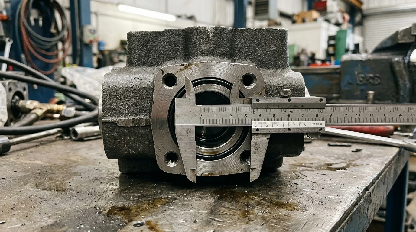
Seating vernier caliper jaws directly in the plane of the hydraulic flange face and O-ring groove eliminates perspective depth offset between the part feature and the measurement scale.
Quantitative perspective parallax error formula and worked example
Under standard pinhole camera projection geometry, the apparent dimensional reading error $\Delta L_app$ (in mm) introduced when the measurement scale sits at an axial depth offset $h_step$ (in mm) behind or in front of a feature of true width $L$ (in mm), photographed at a lens-to-feature working distance $D_cam$ (in mm), is governed by:
$$\Delta L_app = L \times (h_step / D_cam)$$
- Worked arithmetic example (background ruler vs. coplanar caliper): Suppose you measure a $L = 42.0 mm$ hydraulic flange counterbore by resting a flat steel ruler on the valve body $h_step = 18.0 mm$ behind the raised port face while holding a smartphone at $D_cam = 180 mm$. The perspective parallax error is $\Delta L_app = 42.0 \times (18.0 / 180) = 4.20 mm$, making the $42.0 mm$ feature appear as $46.2 mm$ (or $37.8 mm$ if the ruler rests in front)—more than enough to misidentify an ISO 6162 port size or select the wrong seal ring. By clamping vernier caliper jaws directly onto the port groove ($h_step = 1.0 mm$) and stepping back to $D_cam = 600 mm$ with $2\times$ zoom, the apparent error drops to $\Delta L_app = 42.0 \times (1.0 / 600) = 0.07 mm$, keeping the visual reading within $\pm 0.1 mm$ mechanical tolerance.
Rule-of-Thumb 2 — Physical Parallax-Error Focal Distance & Coplanar Scale Threshold:
If camera-to-part working distance is under 300 mm ($D_cam < 300 mm$) with a standard wide-angle smartphone lens or the ruler scale sits more than 5 mm ($h_step > 5 mm$) away from the measured plane → step back to $D_cam = 500 to 600 mm$ using $2\times$ optical zoom and lock vernier caliper jaws directly across the OD/ID centerline because wide-angle close-ups distort circular ports into ellipses and introduce $1.5 to 4.2 mm$ of scale parallax error.
Follow five optical discipline rules when photographing parts on the shop floor:
- Use oblique grazing light for stamped metal, diffused light for printed stickers: Direct on-camera flash reflects off stamped aluminum nameplates and oiled steel shafts, washing out character grooves. Hold a shop worklight at a $30^\circ to 45^\circ$ side angle so shadows define worn engravings.
- Lock the caliper thumb screw before releasing the part: When a second hand is not available to hold both the caliper and the smartphone, lock the caliper's vernier thumb screw on the feature, photograph the jaws seated on the part first, and take a second macro shot of the locked scale reading.
- Keep the camera sensor parallel ($0^\circ$ tilt) to the measured plane: Tilting the phone relative to a bolt circle or connector face foreshortens one axis ($\cos\theta$ cosine error). Frame the port or flange dead-square in the center of the lens.
- Never send screenshots of zoomed gallery previews: Cropping and screenshotting a photo inside a phone gallery strips image resolution down to screen pixel density and introduces JPEG re-compression artifacts. Attach the original camera file directly.
- Isolate loose parts on a clean, high-contrast background: Place dark cast-iron or black rubber components on a light grey or blue workbench mat, and keep parts from different assemblies physically separated.
Takeaway: Seat caliper jaws in the exact plane of the measured feature ($h_step \le 1 mm$) and shoot from $500 to 600 mm$ at $2\times$ zoom to reduce optical parallax error below $0.1 mm$.
How should I photograph hydraulic ports, 4-bolt split flanges, and splined shafts for verification?
Identify heavy-equipment hydraulic and drivetrain interfaces by photographing three physical variables together: flange bolt-hole center spacing (ISO 6162 Code 61 vs. Code 62), thread outside diameter and pitch with sealing seat geometry (ISO 9974, ISO 1179, SAE J514, SAE J1453), and involute spline tooth count $Z$ plus major tip diameter $d_a$ (DIN 5480). On SANY hydraulic pumps, main control valves, swing motors, and travel motors, two assemblies with identical external housings can differ in working pressure series or shaft coupling spline profile.
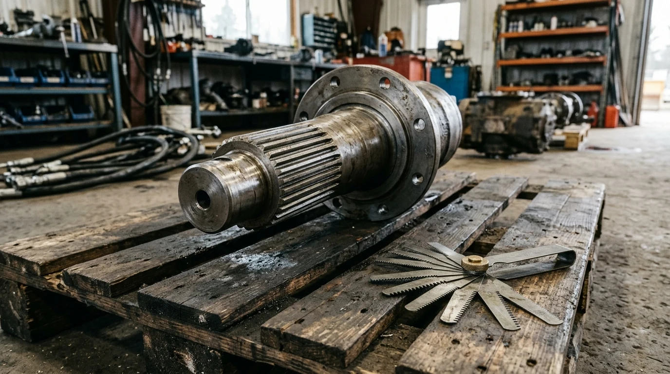
For hydraulic pumps, swing motors, and travel drives, photograph the splined shaft end straight-on for tooth counting, measure the spline major diameter with a caliper, and verify port thread pitch with a pitch gauge leaf.
Rule-of-Thumb 3 — ISO 6162-1 (Code 61) vs. ISO 6162-2 (Code 62) Split-Flange Bolt-Spacing Threshold:
If a hydraulic pump, travel motor, or main control valve port uses a 4-bolt split flange with a nominal port bore between 19 mm and 51 mm ($3/4 in$ to $2 in$, Dash $-12$ to $-32$) → photograph a vernier caliper measuring both the rectangular bolt-hole center spacing (long side $\times$ short side) and the flange head thickness because ISO 6162-1 Code 61 ($3,000 to 3,500 psi$ / $35 MPa$) and ISO 6162-2 Code 62 ($6,000 psi$ / $42 MPa$) share the exact same nominal bore diameter but differ by $3.2 to 19.0 mm$ in bolt pattern spacing.
Rule-of-Thumb 4 — DIN 5480 Involute Spline Tooth Count ($Z$) & Major Diameter ($d_a$) Caliper Lock Threshold:
If ordering a hydraulic pump coupling, swing motor pinion, or travel gearbox shaft without a readable SANY assembly tag → mark Tooth #1 with paint or chalk, photograph the shaft end perpendicular to the axis to verify exact tooth count $Z$, and lock a caliper across the major tip diameter $d_a$ to $\pm 0.1 mm$ per DIN 5480 because a 1-tooth count error ($Z = 21$ vs. $Z = 22$) or module shift ($m = 2.0 mm$ vs. $m = 2.5 mm$) prevents mechanical engagement during installation.
DIN 5480 spline module and pitch diameter verification formula
Under the DIN 5480 $30^\circ$ pressure-angle involute spline baseline used across heavy excavator hydraulic pumps and planetary drives, the nominal pitch diameter $d$ (in mm), module $m$ (in mm), and tooth count $Z$ relate to the caliper-measured external shaft tip (major) diameter $d_a$ (in mm) and radial tip-clearance/profile-shift allowance $c_tip$ via:
$$m = d / Z = (d_a - 2 \times c_tip) / Z$$
- Worked arithmetic example: If an unmarked hydraulic motor shaft has a verified straight-on photo count of $Z = 24 teeth$ and a locked caliper major diameter reading of $d_a = 49.6 mm$ (with standard flank-centered tip allowance $2 \times c_tip = 1.6 mm$), the effective pitch diameter is $d = 49.6 - 1.6 = 48.0 mm$ and the spline module is $m = 48.0 / 24 = 2.0 mm$ (matching standard designation
DIN 5480 W 50 × 2 × 24). That single caliper-and-count check prevents shipping a $Z = 21$, $m = 2.25 mm$ or $Z = 22$, $m = 2.0 mm$ variant.
Use the reference matrix below to capture the exact caliper and thread-gauge photos needed for hydraulic ports, flanges, and splines.
Swipe or scroll horizontally to view the full table.
Interface standard & family | Standard engineering baseline dimensions | What to photograph with caliper / gauge | Dominant field failure mode & mechanical prevention |
|---|---|---|---|
ISO 6162-1 (SAE J518 Code 61) vs ISO 6162-2 (Code 62) 4-bolt split flange | Bolt spacing (Long $\times$ Short): |
| Failure mode: Measuring only the 1" or 1-1/4" port ID ($25 mm$ or $32 mm$), resulting in split-flange halves that miss the manifold bolt holes by $4.8 to 8.0 mm$ or O-ring blowout under $42 MPa$ spikes. Prevention: Always photograph caliper jaws spanning center-to-center across the long bolt spacing. |
ISO 9974 (DIN 3852) parallel metric port & stud end | Metric parallel threads (e.g., | Caliper on male thread major OD (or female bore crest ID) + metric thread pitch leaf ($1.5 mm$ vs $2.0 mm$) + photo of flat spotface or 24° DIN cone | Failure mode: Forcing an ISO 1179 BSPP (G-thread) or SAE UN/UNF fitting into a metric ISO 9974 port, stripping cast-iron manifold threads on the third turn. Prevention: Photograph a metric pitch gauge seated cleanly in the thread flanks alongside the caliper OD reading. |
SAE J514 (JIC 37° flare & ORB O-ring boss) | Unified UN/UNF straight threads (e.g., | Caliper on thread OD + TPI pitch gauge + angled close-up showing either the 37° flared nose cone (JIC) or the chamfered port O-ring seat (ORB) | Failure mode: Cracking flare nuts or leaking under high-pressure vibration by mismatching a 37° JIC cone against a 45° SAE flare or metric 24° cone. Prevention: Photograph the internal/external cone seat profile and confirm thread OD + TPI. |
SAE J1453 (ORFS O-ring face seal) & ISO 1179 (BSPP) | ORFS: flat male face with embedded O-ring groove and UN/UNF straight threads; BSPP: 55° Whitworth parallel threads ( | Macro shot of the flat face O-ring groove + caliper measurement across the thread OD and flat seating face diameter | Failure mode: Confusing an SAE J1453 ORFS flat-face swivel with a BSPP flat-face fitting or missing the face O-ring during field reassembly. Prevention: Capture the face groove and thread pitch together before ordering replacement hose ends or valve adapters. |
DIN 5480 / ISO 4156 involute splined shaft & hub | 30° pressure angle, reference diameter $d_B$, module $m$ ($1.25 to 5.0 mm$), and tooth count $Z$ ($d = m \times Z$) on pump input shafts and travel/swing motor drives |
| Failure mode: Miscounting spline teeth from an angled photo or ignoring profile shift, resulting in a travel motor or pump shaft that binds or strips the coupling sleeve. Prevention: Read Final Drive vs Travel Motor and send both the axial tooth-count photo and locked caliper $d_a$ reading. |
Takeaway: Never order a hydraulic pump, motor, or control valve from port bore diameter alone—photograph caliper measurements across the 4-bolt flange spacing (Code 61 vs. Code 62), thread OD with pitch gauge, and paint-indexed spline teeth.
What specific views are required for SANY filters, electronic controllers, and hydraulic seal kits?
Tailor your close-up photographs to the failure-critical interfaces of each spare-part family: thread and gasket seat dimensions for filters, full multi-pin receptacle cavities and hardware/software revision stickers for controllers, and concentric removal-order layouts plus cylinder rod and bore diameters for seal kits. Follow our companion guide on how to identify a SANY filter, controller, or seal kit alongside the category-specific visual protocols below.
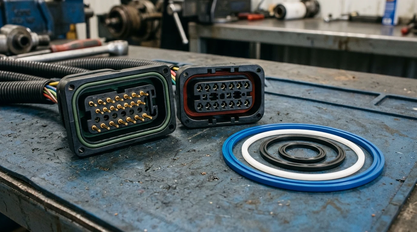
For electrical controllers and switches, capture the connector pin cavities and keying slots straight-on; for hydraulic seal kits, lay out removed piston, rod, backup, and wiper rings concentrically rather than photographing a loose bag of rings.
1. SANY air, fuel, engine-oil, and hydraulic filters
A side-profile photo of a dirty filter canister is insufficient when the printed code is worn off. For spin-on filters (such as B222100000494 Oil Filter, 60282117 Fuel Filter, or B222100000766 Fuel Water Separator), photograph the threaded baseplate straight-on, measure the center thread ID and pitch, measure the rubber base gasket OD and ID, and photograph the water-sensor bowl thread at the bottom if equipped. For cartridge elements (such as 60167841 Hydraulic Oil Filter, 60200365 Hydraulic Return Filter, or 60101257 Oil Suction Filter), photograph both top and bottom end caps (showing whether each end is open or closed with a bypass valve), inner core ID, outer cage OD, and overall length before browsing published SANY filters.
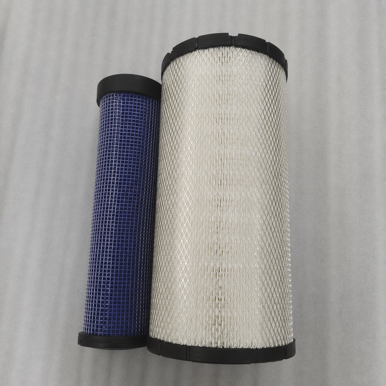
Published catalog reference for 60222811 Air Filter (alternate 60222812) and 60250669 Air Filter (alternate B222100000660K): always photograph the outer primary element and inner safety element side by side, plus both axial sealing faces.
2. SANY monitors, programmable controllers, sensors, and control switches
Two cab displays or ECUs in the SANY controllers catalog—such as 11445949 Monitor Display (SECD-5I-12), 13792488 Monitor Display (SECD-510A-03), B249900001085 Monitor Display, or 140601010331A Programmable Controller—can share an identical outer bezel or aluminum housing while running incompatible pin assignments, CAN-bus baud rates, or factory firmware calibrations. Photograph:
- Every foil sticker, barcode, hardware revision (
HW), software version (SW), and voltage rating (24V DC); - Every connector socket on the back of the unit dead-square ($0^\circ$ angle) so populated pins, blank cavities, and plastic keying ribs are countable;
- The mating machine-side wiring harness plug;
- If the request involves a cab keypad, rocker switch, or rotary throttle dial, review our SANY excavator control switch identification guide to separate a panel membrane softkey from a standalone switch body or proportional joystick.
3. Hydraulic cylinder, swivel joint, and control valve seal kits
A pile of loose black O-rings and polyurethane U-cups in a plastic bag cannot be identified visually. Before tearing down a cylinder or rotary manifold, photograph the stamped cylinder barrel tube number (typically stamped near the head flange or clevis eye) and measure both the chromed piston rod diameter (OD) and cylinder barrel bore (ID) with a caliper. If the old seals are already removed, lay them out in concentric installation order from rod wiper and rod buffer seal to piston assembly rings, and match the parent assembly against our published SANY seal kits—such as 60311647 Bucket Cylinder Seal Kit, 60295019 Arm Cylinder Seal Kit, B260409000279K Swivel Joint Repair Kit, or 60210758 Main Valve Repair Kit.
Swipe or scroll horizontally to view the full table.
Spare-part category | Mandatory photographic views | Required caliper / nameplate inputs | Dominant field failure mode & mechanical prevention |
|---|---|---|---|
Engine, fuel & hydraulic Filters | Canister print/etching, threaded mounting base or both cartridge end caps, inner core, water-bowl thread, and filter head housing tag | Thread OD/ID & pitch, base gasket OD/ID, overall height, outer diameter, and engine model plate (Isuzu, Cummins, Yanmar, Mitsubishi) | Failure mode: Selecting a spin-on filter by canister height and colour alone, causing thread stripping or unfiltered bypass due to wrong standpipe seal ID or bypass valve cracking pressure. Prevention: Photograph both end faces with caliper measurements and pair with the engine data plate. |
Monitors, ECUs & Controllers | Main SANY & maker sticker ( | Exact pin count, keyway slot orientation, hardware/software revision string, and 17-character machine PIN for program matching | Failure mode: Bending connector pins or burning out a 24V driver board by plugging an unprogrammed or wrong-revision ECU into a different serial-break harness. Prevention: Verify both the exact connector pinout photo and whether the controller ships pre-flashed for your machine PIN. |
Cylinder, valve & swivel Seal Kits | Intact OEM bag label (if unopened), cylinder barrel stamping near head/clevis, installed cylinder location, and concentric layout of removed rings | Caliper measurement of chromed rod OD (mm), cylinder barrel bore ID (mm), gland nut style, and machine model + serial number | Failure mode: High-pressure seal extrusion or rod leakage after teardown because mid-series cylinders changed rod diameter by $5 mm$ (e.g., $80 mm$ vs $85 mm$) within the same excavator model. Prevention: Measure rod OD with a caliper and photograph the cylinder tube stamping before ordering the seal kit. |
Riveted sub-vendor plate (Rexroth/Kawasaki/Nabtesco), 3 orthogonal whole-unit views, port faces, regulator solenoids, and paint-marked spline shaft end | ISO 6162 flange bolt spacing (Code 61 vs 62), spline tooth count $Z$ + major OD $d_a$, mounting pilot diameter, and machine PIN | Failure mode: Ordering a bare travel motor when the planetary final drive gearbox failed (or vice versa), or receiving a pump with mismatched regulator pilot ports. Prevention: Clearly define the assembly boundary using our crane, concrete pump, and reach-stacker checklists before quotation. |
If your machine is a crane, concrete pump truck, or port reach stacker rather than a crawler excavator, pair your six-view photographs with the subsystem boundaries in our SANY crane parts supplier checklist, SANY concrete pump parts ordering guide, or SANY reach stacker parts identification guide. When evaluating a rebuilt or dismantled assembly, also require the supplier to send back the bench inspection photos listed in our SANY used parts condition checklist.
Takeaway: Match the photographic evidence to the failure mode of the category—thread and gasket caliper views for filters, perpendicular pinout and firmware tags for controllers, and cylinder tube stampings plus rod/bore diameters for seal kits.
What does a wrong-part shipment cost in machine downtime versus 15 minutes of photo verification?
Investing 15 minutes ($0.25 hr$) to capture the six-view caliper and nameplate photo protocol costs approximately $18.75 in shop technician time, whereas a single wrong-part shipment on a heavy hydraulic or electronic assembly costs over $13,000 in combined excavator standby downtime, round-trip international air freight, restocking penalties, and mechanic rework.
Wrong-part downtime and return-freight cost equation
To evaluate the total operational loss $C_mismatch$ (in USD) of dispatching an unverified spare part that fails physical fitment at the jobsite, sum the four direct cost components:
$$C_mismatch = (T_delay \times H_op \times R_standby) + C_freight + (F_restock \times P_part) + C_rework$$
Where:
-
$T_delay$ = replacement international air-freight & customs re-dispatch delay (days);
-
$H_op$ = scheduled daily machine operating shift (hr/day);
-
$R_standby$ = hourly machine standby & replacement rental/crew idle cost (USD/hr);
-
$C_freight$ = outbound + return international air-freight and customs clearance charges (USD);
-
$F_restock \times P_part$ = supplier restocking/re-inspection fee fraction multiplied by part price (USD);
-
$C_rework$ = field mechanic teardown, crane rigging, and re-installation labor (USD).
-
Worked arithmetic example (1-line calculation): Under a representative export maintenance scenario where an unverified
$2,400hydraulic travel motor or main control valve section ($P_part = 2400 USD$) arrives with an ISO 6162 Code 61 vs. Code 62 port mismatch or wrong spline count, causing $T_delay = 9 days$ of replacement air-freight delay across an $H_op = 8 hr/day$ shift at $R_standby = 165 USD/hr$ standby loss ($9 \times 8 \times 165 = 11,880 USD$), plus $C_freight = 680 USD$ round-trip DHL/air freight, a 15% restocking fee ($0.15 \times 2400 = 360 USD$), and $C_rework = 420 USD$ ($5.6 hr \times 75 USD/hr$), the single wrong shipment costs $C_mismatch = 11880 + 680 + 360 + 420 = 13340 USD$—compared to$18.75($0.25 hr \times 75 USD/hr$) to complete the 6-view photo verification before dispatch.
5-year fleet TCO ledger: unverified single-photo ordering vs. 6-view engineering verification
Consider a 5-year fleet operating baseline for a regional earthmoving or construction contractor running 5 SANY machines (e.g., SY75C, SY135C, SY215C, and SY365C) placing 12 non-routine spare-part orders per year (60 total orders over 5 years, average order value $$1,200$).
Swipe or scroll horizontally to view the full table.
5-year TCO cost component (60 non-routine orders) | Unverified ordering (1 angled photo / casting number only — 15% mismatch rate = 9 wrong shipments) | 6-view photo + PIN + caliper verification protocol (<1.7% mismatch rate = max 1 wrong shipment) | Dominant financial leakage mode & operational prevention |
|---|---|---|---|
Upfront technician photo & caliper verification labor |
|
| Leakage mode: Skipping caliper and nameplate checks to save 12 minutes at RFQ intake. Prevention: Standardize a 15-minute bench photo checklist before submitting any WhatsApp or email inquiry. |
Round-trip air freight & customs duty on wrong shipments |
|
| Leakage mode: Heavy cast-iron hydraulic pumps, cylinders, or undercarriage parts costing $8 to 14 USD/kg$ in dead-loss international air return freight. Prevention: Require supplier pre-shipment caliper and tag photos matching your 6-view submission before air dispatch. |
Supplier restocking fees & non-returnable opened electronics/seals |
|
| Leakage mode: Opening a seal kit bag or plugging in an electronic controller before checking rod OD or pin cavities voids return eligibility. Prevention: Verify package part numbers and pinouts against the old component before breaking factory seals. |
Field mechanic teardown, crane rigging & bay stalls |
|
| Leakage mode: Discovering a 1-tooth spline mismatch or Code 61/62 flange error only after hoisting a $180 kg$ drive or pump into the machine bay. Prevention: Bench-verify spline tooth count $Z$, tip OD $d_a$, and flange spacing on the pallet before hoisting. |
Machine standby downtime & replacement rental loss |
|
| Leakage mode: Machine sitting disassembled in a jobsite trench while waiting a second week for the correct serial-break part. Prevention: Pair every inquiry with the 17-character ISO 10261 PIN plate and sub-vendor tag from Day 1. |
Estimated 5-year cumulative verification & mismatch cost | $66,787.50 |
| Baseline note: Illustrative fleet TCO model under stated hourly standby ( |
Takeaway: A 15-minute investment in six-view caliper and nameplate photography ($18.75 in technician time) prevents $13,340 single-incident wrong-part downtime events and saves over $58,000 across a 5-year, 60-order fleet maintenance cycle.
What to send us for a SANY part identification check and quote
When you submit a part identification request through our quote request form or WhatsApp engineering desk, include the structured evidence package below. Because every item in this table mirrors the physical variables explained above, sending the complete set allows our team to cross-reference your SANY material code, sub-vendor plate, and serial break without back-and-forth delays.
Swipe or scroll horizontally to view the full table.
| Item to send | Why we need it | Example format |
|---|---|---|
| Locks the exact SANY model suffix (e.g., | Uncompressed photo of main riveted nameplate + typed string (e.g., |
| Confirms which circuit or assembly boundary is requested (e.g., travel motor vs final drive gearbox, boom vs arm vs bucket cylinder) | 1 wide installed photo + 3 perpendicular bench photos shot at 500–600 mm ($2\times$ zoom) |
| Cross-references SANY 8-digit ( | Square macro photo of sticker/tag + typed candidate numbers (mark unreadable characters as |
| Verifies multi-pin connector keyways, hydraulic port sealing surface (ISO 6162 flange, ISO 9974 metric, SAE J514/J1453), or DIN 5480 spline tooth count $Z$ | Dead-square ($0^\circ$) photo of connector cavities, port seats, or paint-indexed spline shaft end ( |
| Eliminates perspective parallax when checking Code 61 vs Code 62 bolt spacing, thread OD, cylinder rod/bore diameter, or spline tip OD $d_a$ | Photo of caliper jaws locked flush on the feature + readable millimeter scale ( |
| Allows our Changsha export team to check stock availability, confirm genuine vs OEM/replacement supply class, and calculate air or sea freight | Qty: 1 unit | Supply: Genuine or OEM Rexroth/Kawasaki | Destination: Houston, USA |
How our engineering verification workflow handles your photos
- Send your photos and machine details via the WhatsApp button below or the request-a-quote page, and include any link you found in the SANY part-number lookup or parts catalog.
- Our Changsha export desk cross-checks your evidence against the machine serial range, SANY material code cross-references, and sub-vendor plates, and flags any missing view or dimensional conflict before quoting. We reply within 24 hours.
- You receive a written verification and quote stating the confirmed part number, assembly scope, supply type (read our SANY genuine parts guide for documentation checks), availability, and shipping terms.
Takeaway: Send the six-item evidence package—machine PIN plate, orthogonal part views, sub-vendor plate, perpendicular port/pinout views, locked caliper dimensions, and destination—so we can verify fitment and reply within 24 hours.
Common questions about identifying SANY parts from photos
Is one photo enough to identify a SANY spare part?
One overview photo shows only the general component family and omits the machine serial break, sub-vendor revision tag, connector pin cavities, and port dimensions needed to confirm interchangeability. Always pair the whole-part view with the machine nameplate, component tag, and caliper interface shots in the six-view checklist.
Can I order a hydraulic pump or valve using only the raised casting number on the housing?
Raised sand-cast or forged numbers identify the unmachined iron foundry blank before CNC port threading, spool drilling, and relief-valve pressure calibration. Because one raw casting can be machined into several incompatible SANY part numbers, always photograph the riveted sub-vendor plate, the machine PIN plate, and caliper port measurements.
Why did my ruler photo give a different millimeter reading from a caliper?
Holding a smartphone close to a part while laying a flat ruler on the workbench behind a raised flange or shaft creates optical perspective parallax error. Seat vernier caliper jaws directly in the plane of the measured feature and photograph from 500 to 600 mm using 2x optical zoom to eliminate depth distortion.
Can you identify a SANY part while it is still installed on the machine?
Yes, if the component data plate, SANY label, and external connectors or flange ports are safely visible without disassembly. Send a wide location photo showing which hydraulic circuit or frame section the part mounts to, along with straight-on photos of all accessible tags and the machine nameplate.
How do I distinguish an ISO 6162 Code 61 flange from a Code 62 flange in a photo?
Both flange series share the same nominal port bore diameter, so measuring the hole ID alone causes mismatches. Lock a caliper across the rectangular bolt-hole centers and the flange head thickness; Code 62 high-pressure flanges have wider bolt spacing and thicker heads than Code 61 flanges of the same bore size.
Methodology, standards, and scope
- International engineering standards referenced: Machine Product Identification Number (PIN) structure follows
ISO 10261:2021(17-character alphanumeric PIN for earth-moving machinery). Hydraulic 4-bolt split-flange dimensions followISO 6162-1(SAE J518 Code 61, standard pressure up to $35 MPa$) andISO 6162-2(SAE J518 Code 62, high pressure $42 MPa$). Hydraulic port and fitting thread checks referenceISO 9974(DIN 3852metric parallel ports),ISO 1179(BSPP/Gparallel threads),SAE J514(JIC$37^\circ$ flare andORBstraight-thread O-ring boss), andSAE J1453(ORFSO-ring face seal). Involute spline shaft and hub parameters referenceDIN 5480/ISO 4156($30^\circ$ pressure angle, reference diameter $d_B$, module $m$, and tooth count $Z$). - SANY catalog and service baseline: Part-number formats (
60xxxxxx,1xxxxxxx,B22...,A22...,1406...,1504...) and sub-vendor cross-references (KDRDE5K-31/30C50-140-T,ME229553,8-98312918-0,SECD-5I-12,SECD-510A-03) are compiled from our publishedsanyparts.netcatalog records, SANY Global Maintenance and Support, and SANY Service Cloud serial-binding documentation. - Scope and independent supplier notice: Published standard dimensions and catalog cross-references represent standard engineering baselines under reference conditions; actual machine fitment depends on serial prefix, factory sub-vendor batch, and prior field modifications. SANY Parts (
sanyparts.net) is an independent spare-parts supplier in Changsha, not SANY Group or an authorized dealer. For factory warranty work or official OEM parts books, contact SANY or the authorized distributor for your machine's market.
Last reviewed: Oct 17, 2026