

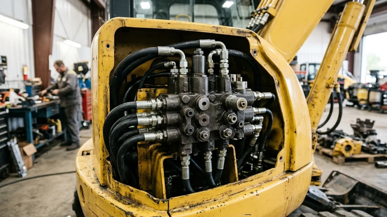
Before replacing a SANY main control valve or condemning a main pump from our SANY hydraulic pumps catalogue, isolate whether low digging power, circuit heat, or cylinder drift originates at the excavator relief valve, the pump compensator, or a bypassing actuator seal.
-
Referring to Figure 12 in Power & Motion Tech's relief valve troubleshooting guide, although the hydraulic pump has traditionally been blamed for almost every operating problem, installing a pressure gauge at the upstream test point—if one is not already in place—determines the maximum pressure at which the system will operate as controlled by the relief valve.
-
In Power & Motion Tech's pressure-relief valves chapter, protecting the pump and the system from excess pressure is the only valid function for a relief valve; when excess pump flow goes to tank it generates heat, and the relief valve in a well-designed hydraulic circuit never relieves oil to tank unless there is a circuit or control malfunction.
-
ISO 4413:2010 (Hydraulic fluid power -- General rules and safety requirements for systems and their components, valid from 05.11.2010 under ICS 23.100.01) specifies general rules and safety requirements for hydraulic fluid power systems and components used on machinery as defined by ISO 12100, covering assembly, installation, adjustment, uninterrupted system operation, and ease and economy of maintenance and cleaning.
-
According to SANY UK & Ireland parts and support documentation, SANY machines use Rexroth pumps and valves alongside Dana transmissions and Cummins engines, and SANY genuine parts are backed with a 12 month warranty period.
Use our SANY excavator nameplate guide to record the machine model and serial number, search known part numbers in the part-number lookup tool, or browse related hydraulic maintenance guides in news and guides.
Published SANY excavator relief valve settings and hydraulic architectures
Compare the hydraulic control architecture and factory relief pressure specifications published for the exact SANY excavator model before connecting a test gauge or turning a relief adjustment screw.
- In our SANY hydraulic pumps category hub, published machines in this cluster use load-sensing on the compact class, where port pattern and the pump tag beat the model name and pumps are often ordered with main control valves and seal kits.
Compact swing boom excavator relief settings and pilot controls
Check the separate implement, travel, swing, and pilot relief settings on compact load-sensing SANY excavators before diagnosing sluggish boom or swing response:
-
In the SANY Europe SY35U specification brochure, the SANY SY35U hydraulic excavator is equipped with a YANMAR 3TNV88F engine rated at 18,2 kW at 2200 rpm, an operating weight of 3855 kg, and a ground pressure of 34 kPa.
-
In the SANY Europe SY35U specification brochure, the hydraulic system is a load sensing system with 2 selectable working modes and variable-capacity piston pumps delivering a maximum flow of 88 L/min.
-
In the SANY Europe SY35U specification brochure, the relief valve setting is 27 MPa for the implement circuits and 27 MPa for the travel circuit.
-
In the SANY Europe SY35U specification brochure, the relief valve setting is 20,6 MPa for the swing circuit (with a swing speed of 9 rpm) and 3,5 MPa for the pilot circuit.
-
In the SANY Europe SY35U specification brochure, the hydraulic cylinders produce a bucket digging force of 30,4 kN and an arm digging force of 18,2 kN, with a boom cylinder diameter x stroke of 84×500 mm, arm cylinder of 75×588 mm, bucket cylinder of 65×538 mm, and blade cylinder of 85×160 mm.
-
In the SANY America Swing Boom Excavators brochure, SANY compact excavators (SY16C, SY26U, SY35U, SY50U, SY60C, and SY80U) range in size from 1.8t to 8.8t and feature hydraulic pilot controls that allow experienced operators to feel the increase in pressure and resistance on the spool.
-
In the SANY America Swing Boom Excavators brochure, models SY16C, SY26U, SY35U, SY50U, SY60C, and SY80U are outfitted with a primary auxiliary circuit (1-way or 2-way), the SY50U and SY80U have secondary auxiliary circuits as well, and the SY35U offers a flow divider (listed in the specification table as a flow diverter valve, new for 2023).
Small crawler excavator load-sensing relief pressures and lifting limits
Review the published operating, travel, and swing pressure limits alongside the hydraulic lifting capacity boundary on small crawler models:
-
In the SANY America SY135C product specifications, the SY135C has an operating weight of 14,870 kg (32,783 lb), a ground pressure of 39.0 kPa (5.7 psi), and an ISUZU AJ-4JJ1X-FT4 engine with 3.0 L (183.0 in3) displacement rated at 77.0 kW (103.3 HP) gross power.
-
In the SANY America SY135C specification sheet, optimized load sensing hydraulics improve operating efficiency by up to 5% and fuel efficiency by up to 10%.
-
In the SANY America SY135C product specifications, the machine uses Load Sensing with Pilot Control hydraulics and an Axial Piston variable displacement main hydraulic pump with a maximum operating flow of 242.0 L/min (63.9 gal/min).
-
In the SANY America SY135C product specifications, the maximum operating pressure is 34.3 MPa (4975 psi) and the maximum travel pressure is 34.3 MPa (4975 psi) on an Axial Piston travel motor with park brake.
-
In the SANY America SY135C product specifications, the Axial Piston swing motor with swing brake has a maximum swing pressure of 25.0 MPa (3626 psi) and a maximum swing speed of 12 RPM, and the hydraulic tank capacity is 150.0 L (39.5 gal).
-
In the SANY America SY135C specification sheet, ISO bucket breakout force is 92.0 kN (20,682 lbf), ISO stick (arm) digging force is 66.0 kN (14,837 lbf), and lifting performance ratings are based on ISO 10567:2007 where lift capacity does not exceed 75% of tipping load on firm, level ground or 87% of hydraulic lifting capacity.
Medium excavator positive-flow relief baselines and sub-series differences
Verify the exact sub-series suffix and engine configuration on medium excavators before comparing digging force or tank capacity figures:
-
In the SANY America SY215LC specification table, the SY215LC has an operating weight of 23,550 kg (51,919 lb), a ground pressure of 36.3 kPa (5.3 psi), and a Cummins QSB6.7 engine (6.7 L displacement) rated at 122 kW (163.6 HP) gross power.
-
In the SANY America SY215LC specification table, the machine uses Positive Flow Control with Pilot Control hydraulics, an Axial Piston variable displacement main hydraulic pump with a maximum operating flow of 444.0 L/min (117.3 gal/min), and a maximum operating pressure of 34.3 MPa (4,975 psi).
-
In the SANY America SY215LC specification table, the Axial Piston travel motor with park brake has a maximum travel pressure of 34.3 MPa (4,975 psi) and a maximum travel effort of 180.0 kN (40,466 lbf), while the Axial Piston swing motor with swing brake has a maximum swing pressure of 27.5 MPa (3,989 psi) and a maximum swing speed of 10.9 RPM.
-
As documented in our SANY hydraulic cylinder seal kit measurement guide, official SANY Group specifications list the SANY SY215C with an arm digging force of 103 kN, a bucket digging force of 138 kN, a 4M50 engine with 118 kW, a 239 L hydraulic tank, and an operating weight of 21.9 t, whereas the SANY SY215C LC has an arm digging force of 115 kN, a bucket digging force of 143 kN, a CUMMINS QSB6.7 engine with 129 kW, a 200 L hydraulic tank, and an operating weight of 23.55 t.
Large excavator negative-flow control and power boost relief settings
Account for both normal operating relief pressure and temporary power boost pressure when testing large negative-flow excavators:
-
In the SANY America SY365C product specifications, the SY365C has an operating weight of 80,910 lb (36 700 kg), a ground pressure of 7.1 psi (48.7 kPa), and a Cummins QSL9 T4F engine with 543.1 in³ (8.9 L) displacement rated at 275 HP (205 kW) gross power.
-
In the SANY America SY365C product specifications, the machine uses Negative Flow Control with Pilot Control hydraulics and an Axial Piston variable displacement main hydraulic pump with a maximum operating flow of 195.5 gal/min (740.0 L/min).
-
In the SANY America SY365C product specifications, the maximum operating pressure is 4,975 psi (34.3 MPa) and the maximum power boost pressure is 5,410 psi (37.3 MPa).
-
In the SANY America SY365C product specifications, the maximum travel pressure is 4,975 psi (34.3 MPa) with a maximum travel effort of 48,109 lbf (214.0 kN), and the maximum swing pressure is 3,989 psi (27.5 MPa) with a maximum swing speed of 9.8 RPM.
-
In the SANY America SY365C product specifications, the ISO bucket breakout force is 43,163 lbf (192.0 kN), the ISO stick (arm) digging force is 37,768 lbf (168.0 kN), and the hydraulic tank capacity is 89.8 gal (340.0 L).
Step-by-step relief valve pressure testing and circuit fault isolation
Follow a structured diagnostic sequence that rules out cab work-mode misselection first, measures upstream pressure against the pump compensator margin second, and isolates service port relief valves from cylinder piston seals third.
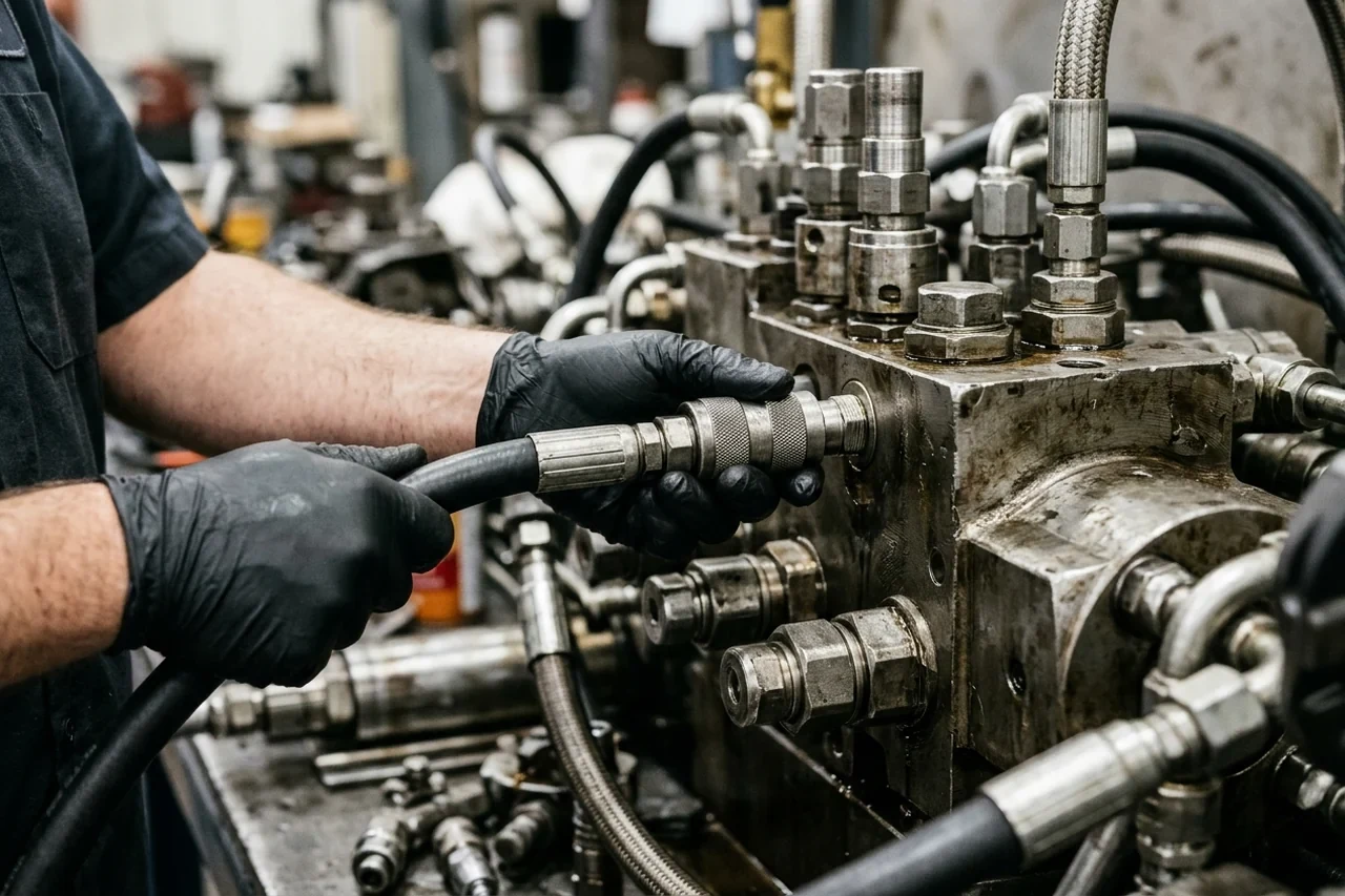
Connecting a pressure test hose coupling to an upstream test port on the main control valve block before adjusting relief cartridges.
Verify cab work modes and attachment flow settings before adjusting valves
Confirm the active work mode and tool selection on the cab monitor before touching any mechanical relief adjustment on the main control valve:
-
In the SANY SY155U Quick Start Guide, the selectable work modes are S (Standard / Normal operation), H (Heavy Duty Mode / Power Boost), L (Light Duty / Lifting), and B (Breaker mode); because mode B prioritises hydraulic oil flow to auxiliary lines over general machine services, if a machine is left in this mode and an operator tries to dig, the machine may feel underpowered and sluggish.
-
In the SANY SY155U Quick Start Guide, entering the tool select menu requires pressing and holding the Auto Idle button on the bottom of the display for 3 seconds to choose among 1 Bucket, 2 Breaker/Hammer, 3 Shear/Grab, Rotate, 4 Quick Hitch, 5 C1 programmable option, and 6 C2 programmable option, and all flows should be verified using a flow meter because figures on the display screen are a guide percentage.
Direct-acting versus pilot-operated relief valves, compensator margin, and vent lines
Evaluate how the relief cartridge design, pump compensator pressure differential, and drain path affect system pressure stability:
-
In Power & Motion Tech's pressure-relief valves chapter, a direct-acting relief valve responds quickly when pressure tries to go above its setting and can be used on pressure-compensated pump circuits to reduce pressure spikes, but opens partially early on fixed-displacement pump circuits, whereas a pilot-operated relief valve has two sections with a normally closed 2-way valve, does not even partially open until system pressure reaches approximately 95% of set pressure, and can unload pumps at pressures below 50 psi.
-
In Power & Motion Tech's pressure-relief valves chapter, when a cylinder stops on a 40 gpm pump circuit where the pump starts compensating at about 1900 or 1950 psi, system pressure spikes during each cycle without a relief valve in the circuit can reach four to ten times the compensator setting and damage the pump and piping after a few hours of operation.
-
In Power & Motion Tech's pressure-relief valves chapter, the relief valve in a pressure-compensated pump circuit must be set 150 to 200 psi higher than the pump compensator: with relief pressure below the compensator setting, pump flow goes to tank and makes heat, and with relief pressure set at compensator pressure, the relief valve starts dumping when the pump starts compensating until the pump fails after a few hours of erratic operation.
-
In Power & Motion Tech's pressure-relief valves chapter, backpressure at the outlet of an internally drained relief valve causes it to shut, whereas externally draining the relief valve eliminates backpressure at the vent port; with the vent open to atmosphere, the relief valve opens at the internal main poppet or piston spring pressure (usually between 20 and 70 psi), and a remote relief valve should be located a maximum of 10 to 15 feet from the main relief.
Separating service port relief cracking from hydraulic cylinder piston-seal bypass
When a boom, arm, or bucket cylinder drifts downward with the joysticks centered, determine whether the service port relief valve is faulty or reacting to pressure intensification across a leaking cylinder piston seal:
- In Power & Motion Tech's hydraulic cylinder drift troubleshooting analysis, if load-induced pressure on the piston side of a cylinder is 2,000 PSI and zero on the rod side when the directional control valve (DCV) is centered, assuming no leakage past the spool, the equalized pressure across a bypassing piston seal may be 3,000 PSI; if the circuit has a service port relief valve set at 2,500 PSI, once the equalizing pressure reaches the cracking pressure of the port relief, the cylinder will creep down.
Main control valve spool silting, solenoid burnout, and filtration maintenance
Inspect sliding spools, pilot stages, and solenoid coils for fine particle silting whenever a control section sticks, fails to shift, or repeatedly burns out electrical coils.
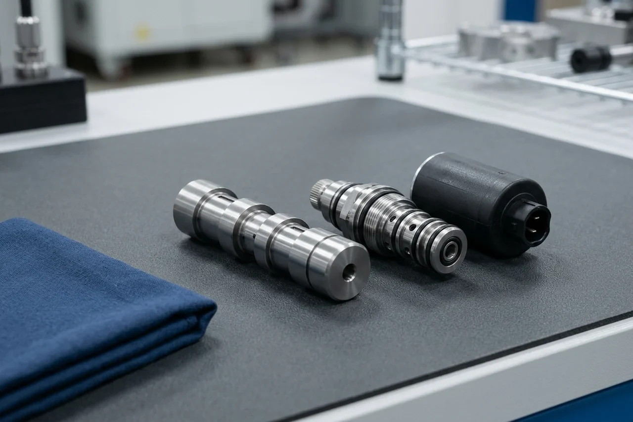
Inspecting a sliding valve spool, cartridge body, and solenoid coil on a clean workshop mat to check for fine contamination scoring.
-
In Power & Motion Tech's analysis of why hydraulic spool valves stick, the radial clearance between the spool and bore in common directional control valves ranges between 3 and 13 microns, and servo and servo-proportional valves are fitted with a sleeve between the spool and bore for high precision.
-
In Power & Motion Tech's analysis of why hydraulic spool valves stick, if the clearances between the spool and bore become invaded by hard particles (silt) or soft particles (varnish and sludge), more force is required to move the spool; according to test data from Eaton Hydraulics cited by Power & Motion Tech, if the radial clearances of a 1/8 inch spool valve operating at 3,000 PSI silt up, 30 pounds of force is required to move the spool whereas a solenoid can only exert 10 pounds of force, producing silt-lock.
-
In Power & Motion Tech's spool valve analysis, if a silt-locked valve is operated by an AC solenoid, the silted spool prevents the solenoid plunger from being completely pulled into its coil, exposing the coil to inrush current for as long as it is energized until the winding insulation burns and the coil shorts out; preventing silt-lock requires keeping the hydraulic oil clean, cool, and dry.
-
In Vickers Inc. silting tests reported by Power & Motion Tech using a CETOP 3, 3-position directional control valve with two lands in the overlapped condition and fluid injected with 5-mm or smaller particles to attain an ISO 4406 contamination class of 20 in the 5 mm or less range, the time to silt-up completely (complete blockage of leakage around the overlapped lands) ranged from one-half to two hours.
-
In the Vickers Inc. sliding-spool silting study, the variables that affect silting are oil contaminant levels, pressure differential across the lands, diameter of the spool, radial clearance from spool to bore, number of lands in overlap condition, length of the overlap, and duration of operation; silting occurs in 2-stage valves in either the pilot or main stage, and proportional solenoids can induce a system-imperceptible dither in the spool.
-
In the SANY SY155U Quick Start Guide Service Intervals Guide, Every 500hrs maintenance requires inspecting (I) Hydraulic Hose Connections and replacing (R) both the Hydraulic Oil Return Filter and the Hydraulic Pilot Oil Filter.
-
In the SANY SY155U Quick Start Guide Service Intervals Guide, Every 4000hrs maintenance requires replacing (R) both the Hydraulic Oil Suction Filter and the Hydraulic Oil, except that hydraulic oil must be changed at 2000hrs if used with attachments, and the Hydraulic Oil Tank service refill capacity is 140 l.
Relief cartridge and control valve O-ring failure modes and assembly rules
Examine removed O-rings and backup rings from relief cartridges and main control valve sections under good lighting to identify the root cause of internal pressure bypass or external weeping.
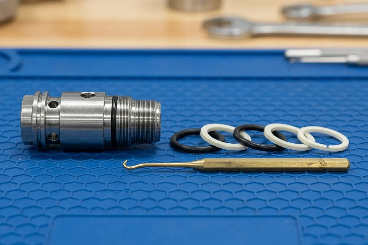
Laying out replacement elastomer O-rings and anti-extrusion backup rings in groove sequence next to a relief valve cartridge.
-
In Fluid Power World's hydraulic O-ring failure guide, extrusion and nibbling produce ragged, chewed edges on the low-pressure side: for pressures above 10 MPa (1,500 psi), total diametral clearance should generally not exceed 0.10 mm (0.004 in) for a standard 70 Shore A compound; moving from 70A to 90A Shore significantly raises the extrusion threshold pressure; install backup rings on the low-pressure side; and relief valve response lag can allow momentary spikes well above nominal operating pressure.
-
In Fluid Power World's hydraulic O-ring failure guide, compression set causes the O-ring to take a permanent flat shape so it no longer springs back when removed; standard NBR compounds typically exhibit 20-40% compression set at 100 degrees C after 70 hours per ASTM D395 Method B (whereas FKM compounds perform significantly better), and squeeze ratios above 30% in static applications or above 16% in dynamic applications generate excessive stress.
-
In Fluid Power World's hydraulic O-ring failure guide, thermal degradation produces radial cracks (heat checking), hardening, and loss of elasticity: NBR is limited to approximately 120 degrees C continuous service, whereas FKM is rated to approximately 240 degrees C and FFKM is rated to approximately 320 degrees C, and rapid compression of fluid at restrictions and across relief valves can generate localized temperatures above the bulk fluid temperature.
-
In Fluid Power World's hydraulic O-ring failure guide, preventing installation cutting across sharp edges, threads, ports, or keyways requires a 15-20 degree chamfer at the bore or rod entry as standard practice, covering threads, splines, and keyways with installation sleeves or tape during assembly, and never stretching an O-ring more than 50% of its inner diameter during installation.
Published SANY main control valve, repair kit, and solenoid spool part numbers
Match the fault learned during pressure testing to the correct SANY parts category—complete hydraulic valve bodies, valve seal kits, or electrical solenoid spools—before requesting a quote.
-
In our SANY main control valves category hub, SANY main control valves are the hydraulic control valve / MCV rather than solenoid valves in general; because section count, fittings, and electrics change across serial ranges, buyers must record the valve label, section arrangement, fittings, and electrical connections for the machine serial range, while failed electronics without the valve body belong on controllers and pumps belong on hydraulic pumps.
-
In our SANY main control valves category hub, model browsing covers SY60C (conventional-tail 6-tonne class parts, kept separate from SY60U), SY75C, SY135C (13-tonne class parts), SY215C, SY365C, SY35U, SY50U (five-tonne class compact excavator parts), and SY155U (short-tail mid-size parts, which must not be treated as an SY155 or SY135C clone).
-
In our SANY seal kits category hub, published seal kit part numbers include Adjuster Seal Kit 60018972K, Arm Cylinder Seal Kit 60295019, Bucket Cylinder Seal Kit 60085580, Bucket Cylinder Seal Kit 60311647, Foot Valve Repair Kit 60340389, Main Valve Repair Kit 60210758, Motor Seal Kit 60210761, Oil Seal BZ4603E, and Swivel Joint Repair Kit B260409000279K.
-
In our parts catalog, 60210758 is a SANY Main Valve Repair Kit under Seal Kits for model reference SY365C; confirm the full model suffix, serial range, and installed valve assembly before ordering.
-
In our parts catalog, 60340389 is a SANY Foot Valve Repair Kit under Seal Kits for model reference SY215C, and buyers should verify the model suffix, serial range, and fitted pedal valve before selecting the kit.
-
In our filter, controller, and seal kit identification guide, because a generic "For this excavator model" description may not identify the fitted cylinder, valve, or motor, resolving a seal kit requires the parent-assembly reference, revision, and the kit's itemised contents, and buyers should ask whether a seal-kit offer covers one repair position or all positions in the parent assembly.
-
In our SANY controllers and solenoid valves category hub, published solenoid valve listings are Solenoid Valve 150401030038B, Solenoid Valve KDRDE5K-31/30C50-140-T, Solenoid Valve T335S3D189, Solenoid Valve Spool 60008386, and Solenoid Valve Spool 60154068, whereas hydraulic valve bodies are categorized under main control valves.
-
In our parts catalog, 60008386 is a SANY Solenoid Valve Spool under Controllers for model reference SY75C; check the machine serial range and removed spool markings before ordering.
-
In our parts catalog, 60154068 is a SANY Solenoid Valve Spool under Controllers for model reference SY215C, requiring verification of the model suffix, serial range, and old valve spool code.
-
In our parts catalog, KDRDE5K-31/30C50-140-T is a SANY Solenoid Valve under Controllers for model reference SY215C; match the full model suffix, serial range, and installed solenoid tag before selecting a replacement.
Prepare your main control valve or relief valve verification request
Include the following identification details when requesting a main control valve assembly, relief cartridge, solenoid spool, or valve seal kit:
- Machine nameplate: attach a clear photograph showing the model designation and complete machine serial number.
- Installed valve tag and section layout: photograph the stamped main control valve nameplate, section arrangement, port fittings, and electrical connectors.
- Removed component reference: capture any part code on the removed relief cartridge, solenoid coil, spool, or seal kit packaging and state whether you need seals for a single repair position or the complete parent valve assembly.
Review our filter, controller, and seal kit identification guide to prepare your photos, or send your machine nameplate and main control valve tag photos on WhatsApp for part number confirmation before ordering.
Sources
- SANY Europe GmbH — Hydraulic Excavator SY35U Official Specification Brochure
- SANY America — SY135C Official Technical Specification Sheet
- SANY America — SY215LC Medium Excavator Official Specifications
- SANY America — SY365C Official Technical Specification Sheet
- SANY America — Swing Boom Excavators Official Brochure (SY16C–SY80U)
- SANY UK & Ireland — SY155U Quick Start Guide
- SANY UK & Ireland — Genuine Parts & Distribution Centre Support
- Power & Motion Tech (Alan Hitchcox) — Think First, Then Troubleshoot, Chapter 9: Relief Valves
- Power & Motion Tech — Fluid Power eBook, Chapter 18: Pressure-Relief Valves
- Power & Motion Tech (Brendan Casey) — How To Troubleshoot Hydraulic Cylinder Drift
- Power & Motion Tech (Brendan Casey) — Why Hydraulic Spool Valves Stick
- Power & Motion Tech (Harry Nowicki, Vickers Inc.) — The Problem of Silting in Sliding-Spool Hydraulic Directional Valves
- Fluid Power World — O-Ring Failure Modes in Hydraulic Systems: Identification, Root Causes and Prevention
- ISO 4413:2010 — Hydraulic fluid power — General rules and safety requirements for systems and their components
- SANYParts.net — SANY Main Control Valves Category Hub
- SANYParts.net — 60210758 SANY Main Valve Repair Kit Identification Page
- SANYParts.net — 60340389 SANY Foot Valve Repair Kit Identification Page
- SANYParts.net — SANY Hydraulic Pumps Category Hub
- SANYParts.net — SANY Seal Kits Category Hub
- SANYParts.net — Hydraulic Cylinder Seal Kit Measurement: Rod, Bore & Cylinder Code
- SANYParts.net — Identify SANY Filters, Controllers and Seal Kits
- SANYParts.net — SANY Controllers & Solenoid Valves Category Hub
- SANYParts.net — 60008386 SANY Solenoid Valve Spool Identification Page
- SANYParts.net — 60154068 SANY Solenoid Valve Spool Identification Page
- SANYParts.net — KDRDE5K-31/30C50-140-T SANY Solenoid Valve Identification Page
Last reviewed: Nov 1, 2026