

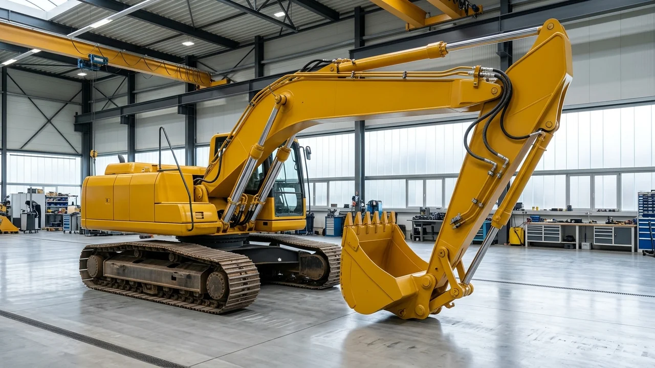
Before ordering a SANY excavator hydraulic cylinder seal kit, verify the installed cylinder assembly, the old kit reference, and the physical metal dimensions. Use the checks below to organize workshop measurements and disassembly records for boom, arm, bucket, and track-adjuster cylinders.
In our seal kits catalogue, cylinder and hydraulic seal kits are identified by the parent assembly and kit reference, and replacement checks should include the cylinder or component label and the relevant drawing dimensions.
For SANY cylinder and hydraulic seal sets, bore, rod diameter, and the old kit number beat a model-only request.
As explained in our filter, controller, and seal kit identification guide, because an excavator model name alone may not identify the fitted cylinder, valve, or motor, resolving a seal kit requires the parent-assembly reference, revision, and the kit's itemised contents.
Keep the machine nameplate record beside the cylinder assembly notes. For more workshop identification articles, visit our news and guides.
Check the cylinder assembly label and kit reference before teardown
Inspect the cylinder barrel, head gland, and clevis area for the parent cylinder assembly label or stamped component reference before opening the gland. Attach photographs of the cylinder marking alongside the existing seal kit part number if a previous parts record is available.
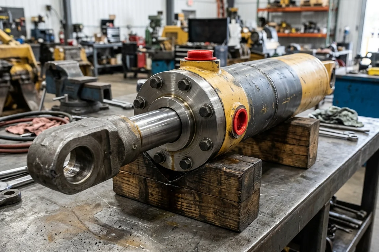
Photograph the parent cylinder assembly marking and head-gland arrangement before disassembly.
Published SANY cylinder and adjuster seal kit references
Each published seal kit in our catalogue is indexed by its part number rather than a machine model name alone.
-
60085580 is a SANY Bucket Cylinder Seal Kit in the Seal Kits catalogue identified by this number, and compatibility is not confirmed from a model name.
-
Catalogue records for this Bucket Cylinder Seal Kit name model code SY365C as a starting reference that requires confirming the full model suffix, serial range, and installed component before selecting the replacement.
-
60295019 is a SANY Arm Cylinder Seal Kit in the Seal Kits catalogue identified by this number, and compatibility is not confirmed from a model name.
-
Catalogue records for this Arm Cylinder Seal Kit name model codes SY135C and SY155U, requiring confirmation of the full model suffix, serial range, and installed component before selecting the replacement.
-
60311647 is a SANY Bucket Cylinder Seal Kit in the Seal Kits catalogue identified by this number, and compatibility is not confirmed from a model name.
-
Catalogue records for this Bucket Cylinder Seal Kit name model code SY215C as a starting reference requiring confirmation of the full model suffix, serial range, and installed component before selecting the replacement.
-
60018972K is a SANY Adjuster Seal Kit in the Seal Kits catalogue identified by this number, and compatibility is not confirmed from a model name.
Separate cylinder seal kits from valve, motor, and swivel kits
Verify the parent component group before submitting a part number from the seal kits catalogue.
In the published Seal Kits listings, part number 60340389 is a Foot Valve Repair Kit and part number 60210758 is a Main Valve Repair Kit.
Published Seal Kits listings also include Motor Seal Kit 60210761, Oil Seal BZ4603E, and Swivel Joint Repair Kit B260409000279K.
Why an excavator model name alone cannot confirm the cylinder seal kit
Even within the same excavator model family, sub-series suffixes and regional configurations carry different working forces, attachments, and hydraulic parameters. Compare the official SANY Group specifications below before assuming two excavators share the same cylinder assembly.
Variant configuration differences within an excavator family
In official SANY Group specifications, the SANY SY215C has an arm digging force of 103 kN, a bucket capacity of 0.93 m³, and a bucket digging force of 138 kN.
The SANY SY215C specification lists a 4M50 engine with 118 kW engine power, a 340 L fuel tank, a 239 L hydraulic tank, and an operating weight of 21.9 t.
The SANY SY215C specification also lists a standard boom of 5.7 m and a standard stick of 2.9 m.
By contrast, in official SANY Group specifications, the SANY SY215C LC has an arm digging force of 115 kN, a bucket capacity of 1.2 m³, and a bucket digging force of 143 kN.
The SANY SY215C LC specification lists a CUMMINS QSB6.7 engine with 129 kW engine power, a 370 L fuel tank, a 200 L hydraulic tank, and an operating weight of 23.55 t.
Digging force and hydraulic differences across SANY excavator classes
Official SANY Group specifications across compact, medium, and large excavators illustrate how arm and bucket load envelopes scale by model code:
-
In official SANY Group specifications, the SANY SY75C has an arm digging force of 35 kN, a bucket capacity of 0.28 m³, and a bucket digging force of 53 kN.
-
In official SANY Group specifications, the SANY SY135C has an arm digging force of 66 kN, a bucket capacity of 0.6 m³, and a bucket digging force of 93 kN.
-
The SANY SY135C specification lists an Isuzu 4JJ1X engine with 78.5 kW engine power, a 240 L fuel tank, a 175 L hydraulic tank, and an operating weight of 14.87 t.
-
In official SANY Group specifications, the SANY SY155U has an arm digging force of 67 kN, a bucket capacity of 0.6 m³, and a bucket digging force of 103 kN.
-
The SANY SY155U specification lists an Isuzu 4JJ1X engine with 75 kW engine power, a 220 L fuel tank, an 85 L hydraulic tank, and an operating weight of 16 t.
-
In official SANY Group specifications, the SANY SY365C (T4f) has 205 kW engine power from a QSL9 engine with 8.9 L engine displacement.
-
The SANY SY365C (T4f) specification lists an arm digging force of 168 kN, a standard stick of 3.17 m, and a standard boom of 6.47 m.
-
The SANY SY365C (T4f) specification lists a 340 L hydraulic tank, a 540 L fuel tank, an operating weight of 36.7 t, a bucket capacity of 1.5 m³, and a bucket digging force of 192 kN.
Measure the metal bore, rod, and housing grooves rather than old rubber rings
When the parent cylinder label is missing or illegible and the cylinder must be dismantled for verification, take your dimensional readings from the machined steel components rather than from used elastomer seals removed from the grooves.
In Fluid Power World O-ring failure analysis guidance, technicians must measure the actual groove depth, width, and surface finish and compare them against the design specification because worn or corroded grooves are a common hidden cause of repeat seal failures.
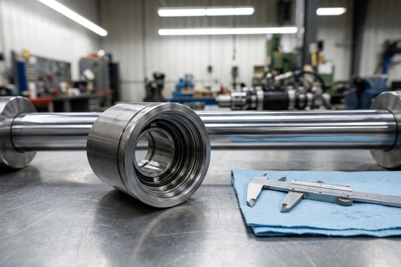
Measure the piston rod, cylinder bore, and machined steel gland grooves directly on the cleaned hardware.
Why measuring removed elastomer rings causes sizing errors
Used rubber and synthetic seals deform in service through permanent compression set, chemical swelling, or chemical shrinkage:
-
In Fluid Power World O-ring failure guidance, an O-ring with compression set takes a permanent flat shape conforming to the groove cross-section and no longer springs back when removed.
-
In that Fluid Power World guidance, standard NBR compounds typically exhibit 20-40% compression set at 100 degrees C after 70 hours per ASTM D395 Method B.
-
Squeeze ratios above 30% in static applications or above 16% in dynamic applications generate excessive stress that accelerates permanent set.
-
In Fluid Power World chemical-degradation guidance, a swollen O-ring appears oversized, soft, and spongy and may extrude from the groove even at low pressure, whereas a shrunken O-ring appears undersized, hard, and brittle.
Check clearance, surface roughness, rod condition, and installation chamfers
While the cylinder is open on the bench, inspect the mating metal surfaces and entry chamfers alongside the groove dimensions:
-
In Fluid Power World extrusion guidance, for pressures above 10 MPa (1,500 psi), total diametral clearance should generally not exceed 0.10 mm (0.004 in) for a standard 70 Shore A compound.
-
In Fluid Power World reciprocating seal guidance, reducing surface finish roughness on the dynamic sealing surface to 0.2-0.4 micrometers Ra for reciprocating applications helps prevent spiral failure.
-
In Trelleborg Sealing Solutions hydraulic leakage guidance, ideal relative material ratio (Rmr) values for a counter surface typically range between 50-70%, ensuring adequate seal support while allowing for proper lubrication.
-
In Fluid Power World hydraulic cylinder failure guidance, a cylinder rod with any scoring, pitting, or bending should be replaced if a simple re-chroming will not do the job, and when the cylinder is in pieces, every single seal should be replaced with the same construction and material.
-
In Fluid Power World installation guidance, a 15-20 degree chamfer at the bore or rod entry is standard practice, and an O-ring must never be stretched more than 50% of its inner diameter during installation.
Record removed seal groove order, back-up rings, and drift symptoms
When a cylinder is dismantled for seal identification, workshops should keep the parent-assembly identity, workshop measurements, and the removed seal order together.
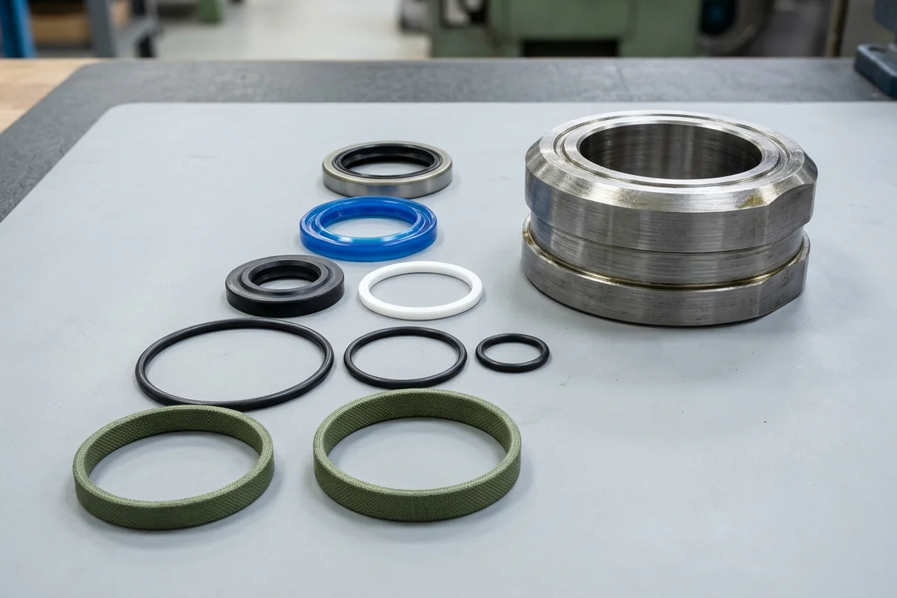
Lay out the removed wiper, primary rod seal, buffer seal, back-up rings, and wear rings in groove order for the workshop record.
Rod seal subsystem order and buffer-seal back-up ring function
In SKF heavy-duty hydraulic cylinder guidance, the rod seal subsystem in a typical sealing arrangement includes a buffer seal, a primary rod seal, and a wiper.
In SKF buffer-seal test reporting, pressure spikes in heavy-duty applications can exceed 600 bar and should be handled by the buffer seal, while a polyurethane U-cup primary rod seal handles pressures up to 400 bar.
In SKF buffer rod seal guidance, polyurethane lip seals with a thermoplastic back-up ring are suited to heavy-duty applications where pressure spikes climb past 600 bar.
-
In the SKF buffer-seal test comparison, if the ratio of intermediate pressure to system pressure between the buffer seal and primary rod seal is above 60%, the buffer seal will not absorb pressure spikes.
-
In the SKF test results for a lip buffer seal without a back-up ring, intermediate pressure equaled the system pressure over 96% of the entire testing distance, leaving no buffering capability available.
-
In that SKF test, when paired with the lip buffer seal without a back-up ring, the primary rod seal already showed wear and extrusion after a testing distance of 90 km.
-
By contrast, in the SKF test results, friction-optimized buffer seal 2 maintained a relatively low intermediate pressure below 50 bar at 250 bar system pressure.
Static groove series, Shore hardness, and elastomer service temperature
Record any surviving seal material codes and groove series when preparing the replacement worksheet:
-
In Fluid Power World static seal reporting, the Hallite 668 static seal range was expanded to include both imperial and metric ISO grooves.
-
In Fluid Power World seal design guidance, most fluid power seals are on the Shore A scale and range from 70A to 90A in hardness.
-
In Fluid Power World elastomer guidance, NBR is limited to approximately 120 degrees C continuous service, while FKM is rated to approximately 240 degrees C and FFKM is rated to approximately 320 degrees C.
Distinguish internal piston-seal drift from external rod-seal leakage
Before ordering a rod-gland seal kit for a cylinder that creeps under load without external oil dripping at the wiper, verify how internal piston-seal bypass behaves in a blocked cylinder circuit.
In Brendan Casey's hydraulic cylinder drift analysis, if the load-induced pressure on the piston side of the cylinder was 2,000 PSI and zero on the rod side when the DCV was centered, assuming no leakage past the spool, the equalized pressure may be 3,000 PSI depending on the ratio of the areas.
In that cylinder drift analysis, as pressure starts to equalize across the piston seal and the increasing static pressure on the piston side of the cylinder reaches the cracking pressure of the port relief, the cylinder creeps down.
Prepare your SANY hydraulic cylinder seal kit enquiry
Assemble the following records before requesting a cylinder seal kit compatibility check:
- Machine identification: attach clear photographs of the excavator nameplate and model suffix.
- Parent cylinder assembly: include the cylinder barrel or head-gland label, stamped assembly code, and old seal kit part number if known.
- Cylinder position and fault observation: state whether the cylinder is a boom, arm, bucket, or track-adjuster cylinder, and describe external gland leakage or internal drift findings.
- Metal hardware measurements: list the measured piston rod diameter, cylinder tube bore diameter, and the gland and piston groove widths and depths.
- Removed seal order: attach a laid-out photograph showing the sequence and orientation of the wiper, primary rod seal, buffer seal, back-up rings, piston seals, and wear rings.
Use our SANY excavator nameplate guide to capture the machine serial details, or send your cylinder label and workshop measurement record on WhatsApp for a seal kit check.
Sources
-
SANYParts.net — Seal Kits Category Hub
-
SANYParts.net — 60085580 SANY Bucket Cylinder Seal Kit Identification Page
-
SANYParts.net — 60295019 SANY Arm Cylinder Seal Kit Identification Page
-
SANYParts.net — 60311647 SANY Bucket Cylinder Seal Kit Identification Page
-
SANYParts.net — 60018972K SANY Adjuster Seal Kit Identification Page
-
SANYParts.net — Identify SANY Filters, Controllers and Seal Kits Guide
-
SANY Group — SY215C Medium Excavator Official Specifications
-
SANY Group — SY215C LC Medium Excavator Official Specifications
-
SANY Group — SY365C (T4f) Large Excavator Official Specifications
-
SANY Group — SY135C (Tier 4F & Stage V) Small Excavator Official Specifications
-
SANY Group — SY155U (Tier 4F & Stage V) Small Hydraulic Excavator Official Specifications
-
SANY Group — SY75C Small Excavator Official Specifications
-
Fluid Power World — Hallite 668 Twin Lip Static Seal for Hydraulic Cylinder Gland and Piston Grooves
-
Power & Motion Tech / SKF — How Buffer Rod Seals Influence Rod Seal Performance
-
Power & Motion Tech / SKF — Test Results Compare Buffer Seals for Hydraulic Cylinders
-
Power & Motion Tech (Brendan Casey) — How To Troubleshoot Hydraulic Cylinder Drift
-
Power & Motion Tech / Trelleborg Sealing Solutions — Beyond the Seal: A Systems-Approach to Eliminating Hydraulic Leakage
-
Fluid Power World — A Designer's Guide to Fluid Power Seals
-
Fluid Power World — O-Ring Failure Modes in Hydraulic Systems: Identification, Root Causes and Prevention
-
Fluid Power World (Josh Cosford) — What are the most common causes of hydraulic cylinder failures?
Last reviewed: Oct 28, 2026