

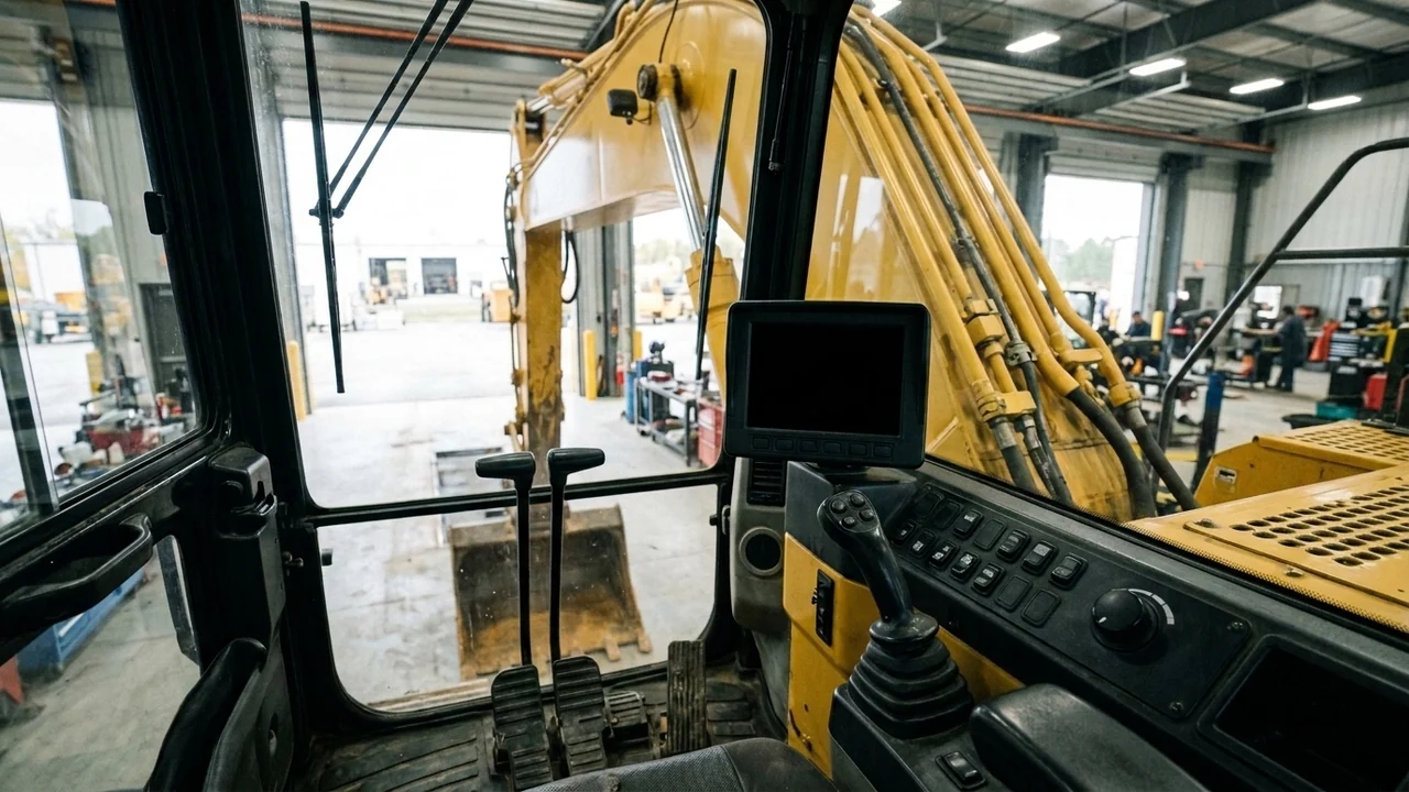
Troubleshooting SANY excavator fault codes starts with separating cab display warnings, operator work-mode settings, and wiring harness faults from genuine electronic module failures before ordering parts from our SANY controllers catalogue.
Use the part-number lookup tool or part search when you already have a verified part reference, or explore additional field identification workflows in news and guides.
Reading SANY monitor display callouts, colour-coded alerts, and setup states
Inspect the cab monitor display positions, icon severity colours, and active operator settings below to distinguish normal status indicators and setup traps from active hardware faults.
-
On the SANY SY155U Display layout, screen positions 01 to 09 identify 01 Error Message, 02 Machine Emergency Stop Active, 03 GPS Active, 04 Date And Time, 05 Tool Selection Display, 06 DEF Level Gauge, 07 Engine Speed (RPM), 08 Engine Coolant Temperature, and 09 Camera Display.
-
On the SANY quick start display layout, screen positions 10 to 17 identify 10 Work Mode, 11 Throttle Position, 12 Fuel Gauge, 13 Work Mode Selection, 14 Auto Engine Idle, 15 Travel Speed Selection, 16 Camera Settings, and 17 Main Menu.
-
In the SANY quick start display icon table, Grey indicates Normal Status, Green indicates Escape Mode or Automatic Regeneration, Yellow indicates Manual Regeneration Required or Manual Regeneration in Progress, and Red indicates Engine Power Limited, Engine Torque Alarm, 1HZ Red Primary Limitation of Engine Torque, or 3HZ Red Ultimate Limitation of Engine Torque.
-
In the SANY quick start display icon table, Red alerts include Heat, DPF Change Required, and Too Low Engine Oil Pressure, while Yellow alerts include Hight Exhaust Temperature, Manual Regeneration Required, Manual Regeneration in Progress, and Oil Change Required.
-
In the SANY quick start display icon table, Green indicates Maintenance Required, Yellow indicates Error Code or Primary Overload Alarm, Grey indicates Normal Status or Battery Being Charged, and Red indicates Ultimate Overload Alarm, Low Battery Voltage, or Low Battery.
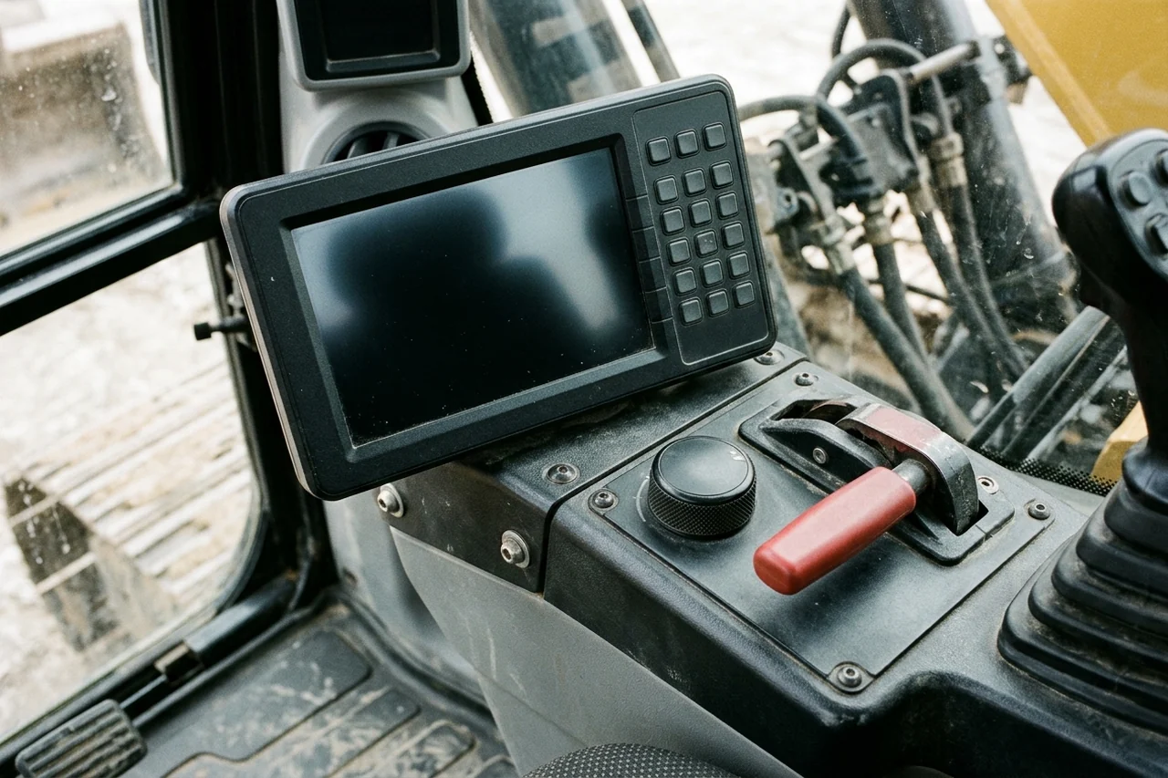
Check the cab monitor display, softkey pad, rotary throttle dial, and hydraulic isolation lever positions before diagnosing an apparent power loss or control fault.
Work modes, exhaust regeneration inhibits, tool flow setup, and warm-up checks
Verify that sluggish digging, exhaust warnings, or unstored attachment flow changes are not caused by the operating mode or keypad state:
-
In the SY155U Work Modes table, mode S is Standard / Normal operation, mode H is Heavy Duty Mode (Power Boost), mode L is Light Duty / Lifting, and mode B is Breaker mode, which prioritises hydraulic oil flow to auxiliary lines over general machine services and the machine may feel underpowered and sluggish if left active when trying to dig.
-
During exhaust regeneration, pressing the Inhibit switch stops the regen and illuminates the Regen Inhibit light on the display; all inhibits are recorded within the machine ECU, and multiple inhibits will lead to a service regen being required or may result in damage to the exhaust system; damage caused in this way is NOT covered by warranty.
-
In the SY155U QUICK START GUIDE, a manual regeneration is only available if the machine requests one, which it only does if automatic regenerations have been inhibited or cancelled.
-
During manual regeneration, the safety lever must be down, the throttle dial must be on 1, the Manual Regen light stays illuminated throughout the process, and operators must not leave the machine unattended or open the bonnet because exhaust temperatures may exceed 700 degrees centigrade.
-
To enter the Tool Selection menu on the display, the operator presses and holds the Auto Idle button on the bottom of the display for 3 seconds, navigates with the soft keys, and presses the Tick soft key when highlighted green to store options 1 Bucket, 2 Breaker/ Hammer, 3 Shear/ Grab, Rotate, 4 Quick Hitch, 5 C1, or 6 C2.
-
In the SY155U QUICK START GUIDE Tool Setup procedure, accessing tool flow setup requires switching the machine ignition on with the engine off, selecting the required tool, and placing the hydraulic isolation lever in the work position; AUX1+ is right handle slider to right (Is RR) and AUX1- is right handle slider to left (Is RL).
-
On the tool flow setup screen, AUX2+ is left handle slider to right (Is LR) and AUX2- is left handle slider to left (Is LL), and figures on the display screen are a guide percentage that should always be verified using a flow meter to ensure the attachment flow is correct.
-
In the SY155U QUICK START GUIDE Softkey Pad layout, buttons 1 to 8 are 1 Start-Stop Switch, 2 Overload Alarm Switch (Optional), 3 Alarm Switch, 4 Amber Beacon Switch, 5 Front Work Lights Switch, 6 Rear Work Light Switch (Not Equipped), 7 Auto-deceleration Switch, and 8 Regeneration Inhibit Switch.
-
On the Softkey Pad layout, buttons 13 to 16 are 13 Work Mode Change, 14 Travel Speed Selection, 15 Manual Regeneration Switch, and 16 Engine Escape Mode Switch, while the Arm Rest houses 1 Ignition Switch, 2 Hydraulic Dozer Blade, 3 Travel Speed Selection Button, 4 Windscreen Wiper, 5 Windscreen Wash, and 6 Engine Speed Throttle Dial.
-
SANY Global's mini excavator operation guide states that before starting, operators turn the key to the ON position and wait 3–5 seconds to allow the fuel pump to prime; after the instrument panel completes self-checks (no red light alerts) and all joysticks are confirmed in neutral, turn to START to crank the engine.
-
SANY Global's mini excavator operation guide instructs operators to let the engine idle for 3–5 minutes after start (5–8 minutes in winter) until normal operating temperatures are indicated: coolant above 60°C and hydraulic oil above 40°C.
Why SANY fault codes and ECU configurations vary across models and regional builds
Compare the engine makers, aftertreatment configurations, hydraulic pressures, and regional software rules below to see why diagnostic trouble codes and controller firmware should not be assumed interchangeable across different SANY models or markets.
-
In SANY America's Swing Boom Excavators brochure, the SY16C, SY26U, and SY35U run without a DPF, while the line also includes the SY50U, SY60C, and SY80U; whichever model is right for you is backed by SANY's 5-year/5,000-hour warranty.
-
In SANY America's Swing Boom Excavators brochure, the SY35U through the SY80U offer standard enclosed, climate-controlled cabs and digital displays with on-board diagnostics, and all models are equipped with hydraulic pilot controls, pattern-change valve, and auxiliary flow circuits.
-
In SANY America's Swing Boom Excavators brochure, a magnetic beacon and travel alarm alert workers during machine movement, bright LED lights provide visibility, and a ground-accessible emergency cutoff switch completely shuts down the machine in case of emergency.
-
According to the SANY Europe HYDRAULIC EXCAVATOR SY35U brochure, the SY35U uses a YANMAR 3TNV88F engine (1,642 L displacement) rated at 18,2 KW/2200 RPM, with a 3855 KG operating weight and 34 KPA ground pressure.
-
In the SANY Europe SY35U hydraulic specifications, the relief valve settings are 27 MPa for implement circuits, 27 MPa for travel circuit, 20,6 MPa for swing circuit, and 3,5 MPa for the pilot circuit.
-
In the SANY Europe SY35U standard equipment list, the operator environment and safety package includes a Multi Language Display, a 12v outlet, a Battery master switch, a Travel Alarm and Beacon, and an Engine emergency cut off from ground.
-
According to SANY Global's SY135C(Tier4 F & Stage Ⅴ) specification page, that SY135C small excavator uses an Isuzu 4JJ1X engine model (2.999 L engine displacement, 78.5 kW engine power), a 240 L fuel tank, a 175 L hydraulic tank, a 27 L radiator, and has a 14.87 t operating weight.
-
According to SANY Global's SY215C specification page, that SY215C medium excavator configuration uses a 4M50 engine model (4.9 L engine displacement, 118 kW engine power), a 340 L fuel tank, a 239 L hydraulic tank, a 29 L radiator, and has a 21.9 t operating weight.
-
According to SANY Global's SY365C(T4f) specification page, the SY365C(T4f) large excavator uses a Cummis QSL9 engine model (8.9 L engine displacement, 205 kW engine power), a 48 L radiator, a 340 L hydraulic tank, a 540 L fuel tank, and has a 36.7 t operating weight.
Regional software divergence and scheduled electrical maintenance
Verify machine origin and maintenance history when diagnosing recurring electrical or aftertreatment fault codes, and see our SANY excavator chassis number and nameplate guide if the cab plate is missing or mismatched:
-
SANY UK & Ireland official guidance on used or imported SANY machines states that machines built for markets outside the UK and Ireland can differ in UKCA and/or CE conformity, Stage V emissions compliance, machine specification and safety systems, software configuration, and technical documentation and operator manuals.
-
SANY UK & Ireland recommends checking the machine serial number (PIN), Declaration of Conformity, UKCA and/or CE documentation, emissions compliance status, service history, and warranty and support eligibility before purchasing through an auction, independent dealer, or private seller.
-
In the SY155U Service Intervals Guide, Every 500hrs* requires replacing the Fuel Filter, Fuel Pre-filter, Hydraulic Oil Return Filter, and Hydraulic Pilot Oil Filter, Every 1000hrs requires replacing the DEF Tank Filter and DEF Pump Filter, and Every 2000hrs requires inspecting the Alternator and Starter.
-
SANY Global's Excavator Maintenance Process Guide specifies monthly electrical system inspection: checking for wear and damage of various electrical connections, circuits, and fuses, and ensuring that all indicator lights and gauges function normally.
-
SANY Global's Excavator Maintenance Process Guide states that complete records of daily inspections, maintenance, and parts replacement facilitate tracking equipment conditions and troubleshooting recurring faults, while serving as valid warranty documentation.
Isolating wiring harness, CAN bus, switch, and solenoid faults before replacing a controller
Check the machine-control, electromagnetic compatibility, CAN bus, and multimeter isolation rules below before condemning an expensive electronic control unit or cab display.
-
ISO 15998:2008 specifies performance criteria and tests for functional safety of safety-related machine-control systems (MCS) using electronic components in earth-moving machinery and its equipment, as defined in ISO 6165.
-
ISO 13766-1:2018 deals with general EMC requirements under typical electromagnetic environmental conditions (while ISO 13766-2:2018 deals with functional safety EMC), and evaluates electrical/electronic subassemblies (ESA) for broadband and narrowband electromagnetic interference, electromagnetic field immunity, electrostatic discharge, and conducted transients.
-
ISO 11898-1:2024 specifies the controller area network (CAN) data link layer (DLL) and physical coding sub-layer (PCS), featuring data fields of up to 2048 byte when the CAN extended data field length (XL) frame format is used.
-
ISO 16750-2:2023 states that electrical loads are independent from the mounting location, but can vary due to the electrical impedance—including both the resistance and the inductance—in the vehicle wiring harness and connection system.
-
Canfield Connector's GTT Series GatorMate J1939 CAN Bus terminator features a factory-encapsulated 120 ohm resistor in accordance with SAE standards, available in 2, 3, or 4 pin plug or receptacle configurations with IP67, IP69, and IP69K protection and an operating temperature range of 20 C to 80 C.
-
The Danfoss CAN 2 Current (C2C) solenoid-mounted microcontroller is compliant with ISOBUS and SAE J1939 protocol, and has configurable parameters including guarding, dither, minimum, maximum, and hold current with an IP67 ingress rating.
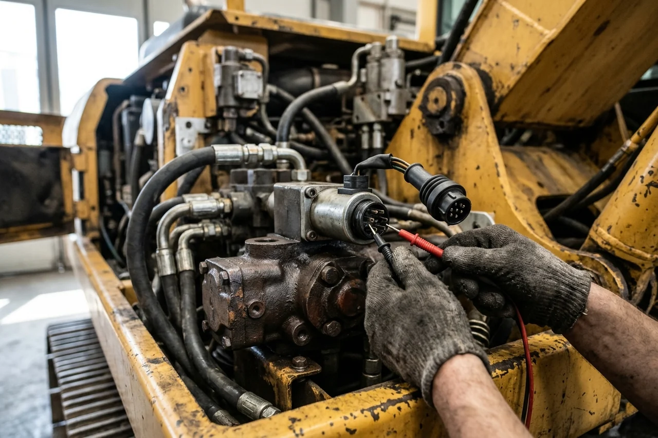
De-energize the electrical circuit and unplug the component connector before measuring continuity or coil resistance so parallel harness paths do not distort the reading.
Digital multimeter continuity and resistance isolation procedure
Follow this de-energized isolation procedure when checking harness conductors, control switches, relays, and solenoid coils:
-
Fluke's continuity test procedure states that when the dial is turned to Continuity Test mode—typically combined with resistance (Ω)—with the test probes separated, the multimeter's display may show OL and Ω.
-
In Fluke's continuity testing steps, the black test lead is inserted first into the COM jack and the red lead into the VΩ jack; leads are always removed in reverse order (red first, then black), and with the circuit de-energized the component must be isolated from other components in the circuit.
-
Fluke's continuity testing guide explains that the beep is triggered based on the resistance of the component being tested, influenced by the multimeter's range setting: at a 400.0 Ω range setting, a multimeter typically beeps if the component has 40 Ω or less resistance.
-
Fluke's resistance measurement guide states that in general, the resistance of components used to control circuits (such as switches and relay contacts) starts out very low and increases over time due to wear and dirt, whereas loads such as motors and solenoids decrease in resistance over time due to insulation breakdown and moisture.
-
Fluke's resistance measurement guide states that power to the circuit must be turned off and any capacitor discharged before taking a resistance reading, and best results are achieved if the component is removed from the circuit so readings are not affected by other components in parallel.
-
Fluke states that for very low-resistance measurements, relative mode (REL, zero, or Delta Δ) automatically subtracts test lead resistance—typically 0.2 Ω to 0.5 Ω—so that when test leads are shorted together, the display should show 0 Ω.
Pre-replacement verification for SANY controllers, monitor displays, sensors, and solenoid valves
Review our published Controllers hub listings and identification rules below to match the faulty assembly against your machine serial number and old-part markings before placing an order.
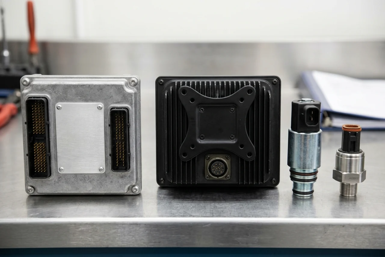
Compare the physical housing label, multi-pin connector arrangement, and component category before submitting a replacement inquiry.
Published SANY controller, monitor display, sensor, solenoid, and throttle motor references
Check the exact part reference and model association in our catalogue before requesting a quote:
-
Our SANY Controllers catalog separates control units, monitors, and integrated boxes from sensors, solenoid valves, and throttle motors: for a controller or monitor, buyers send the label, connector face, and any software marking with the machine serial plate; for a sensor, solenoid valve, or throttle motor, buyers send the part number on the old part.
-
In our Control units, monitors and integrated boxes group, the published Integrated Box references are 12318635, 13534903, and 13558716, and the Monitor Display references include 11445949 and 11888261.
-
In our Control units, monitors and integrated boxes group, the additional published Monitor Display references are 135-215-330, 13792488, and B249900001085, and the Programmable Controller reference is 140601010331A.
-
In the Sensors group of our SANY Controllers catalog, the published references are Camshaft Speed Sensor 60311981, Common Rail Pressure Sensor ME229553, and Temperature Sensor 60033039.
-
In the Solenoid valves and Throttle motors groups of our SANY Controllers catalog, the published references are Solenoid Valves 150401030038B, KDRDE5K-31/30C50-140-T, and T335S3D189, Solenoid Valve Spools 60008386 and 60154068, and Throttle Motor KP56RM2G-020.
-
In our SANY Controllers catalog FAQ, when ordering controllers, buyers should send a photo of the label and the connector or sensor body plus the catalogue part number and machine serial plate, and fault codes help when the part is a controller or monitor.
-
In our parts catalog, SANY Monitor Display 11888261 is listed under Controllers with model code SY215C, and buyers must confirm the full model suffix, serial range, and installed component before selecting the replacement.
-
In our parts catalog, SANY Programmable Controller 140601010331A is listed under Controllers with model code SY365C; confirm the full model suffix, serial range, and installed unit before ordering.
-
In our parts catalog, Monitor Display 11445949 is listed under Controllers for model codes SY135C and SY215C.
-
In our parts catalog, Monitor Display 13792488 is listed under Controllers for model code SY75C.
-
In our parts catalog, Solenoid Valve KDRDE5K-31/30C50-140-T is listed under Controllers for model code SY215C.
-
In our parts catalog, Solenoid Valve 150401030038B is listed under Controllers for model code SY365C.
-
In our parts catalog, Common Rail Pressure Sensor ME229553 is listed under Controllers for model code SY215C.
-
In our parts catalog, Camshaft Speed Sensor 60311981 is listed under Controllers for model code SY365C.
-
In our parts catalog, Temperature Sensor 60033039 is listed under Controllers for model codes SY135C and SY75C.
-
In our parts catalog, Throttle Motor KP56RM2G-020 is listed under Controllers for model codes SY155U and SY60C.
Hardware, software, connector, and label verification checklist
Confirm these configuration and identification boundaries before approving a quotation:
-
Our guide to identifying filters, controllers, and seal kits states that for a Controller, the case and connectors do not describe the complete configuration; buyers must provide the full label, machine serial, hardware/software identifiers, and setup requirements.
-
Our controller identification checklist instructs buyers to photograph the full controller label, all connectors, and installed location, record hardware revision and any software, machine configuration, or calibration identifier in the service record, and ask whether the quoted unit needs programming, calibration, or pairing.
-
Our control switch identification guide warns that a SANY excavator control switch request might concern a panel softkey, a separate switch body, or an electronic controller, and instructs buyers to keep operator symptom descriptions separate from what the technician has confirmed is faulty.
-
Our control switch identification guide states that a similar plug shape is only a comparison clue and does not confirm electrical compatibility; supply voltage, contact arrangement, terminal assignment, and required programming must be confirmed using the exact unit's documentation.
-
Our part-number lookup guide separates Casting or moulded mark and Component maker's plate, instructing buyers to record maker, type, serial, and any revision fields and cross-reference the fitted pump, motor, engine, or controller separately from the machine.
Prepare your SANY controller or monitor verification request
Include the following records when submitting a parts verification inquiry:
- Machine nameplate and serial: attach an uncropped photograph of the machine nameplate together with the exact model suffix and serial number.
- Old-part label and maker's plate: attach a clear, square-on photograph of the complete controller, monitor, sensor, solenoid valve, or throttle motor label using our part photography guide.
- Connector faces and installed location: attach photographs of all rear connector cavities, pin layouts, and the mounting position on the excavator.
- Active display alerts and setup scope: include a photograph of any fault code or warning icon visible on the monitor display and state whether you require a bare module or a programmed unit.
Browse our SANY controllers catalogue to review individual identification pages, or send your fault code, nameplate, and component label photos on WhatsApp for pre-order verification.
Sources
- SANY UK & Ireland — SY155U Quick Start Guide Official PDF
- SANY America — Swing Boom Excavators Official Brochure
- SANY Europe GmbH — Hydraulic Excavator SY35U Official Specification Brochure
- SANY UK & Ireland — Used or Imported SANY Machines Official Guidance
- SANY Group — Excavator Maintenance Process Guide
- SANY Group — How to Operate a Mini Excavator for Beginners
- SANY Group — SY215C Medium Excavator Official Specifications
- SANY Group — SY365C (T4f) Large Excavator Official Specifications
- SANY Group — SY135C (Tier4 F & Stage V) Small Excavator Official Specifications
- EVS Standard Repository — ISO 15998:2008 Earth-moving machinery Machine-control systems using electronic components
- EVS Standard Repository — ISO 13766-1:2018 Earth-moving and building construction machinery Electromagnetic compatibility
- EVS Standard Repository — ISO 11898-1:2024 Road vehicles Controller area network data link layer and physical coding sublayer
- EVS Standard Repository — ISO 16750-2:2023 Road vehicles Environmental conditions and testing for electrical and electronic equipment
- Fluke Corporation — How to Test for Continuity with a Digital Multimeter
- Fluke Corporation — How to Measure Resistance with a Digital Multimeter
- Fluid Power World — Canfield Connector GTT Series GatorMate J1939 CAN Bus Terminators
- Power & Motion — Danfoss Power Solutions CAN 2 Current Solenoid-Mounted Microcontroller
- SANYParts.net — SANY Controllers Category Hub
- SANYParts.net — Monitor Display 11888261 Identification Page
- SANYParts.net — Programmable Controller 140601010331A Identification Page
- SANYParts.net — Monitor Display 11445949 Identification Page
- SANYParts.net — Monitor Display 13792488 Identification Page
- SANYParts.net — Solenoid Valve KDRDE5K-31/30C50-140-T Identification Page
- SANYParts.net — Solenoid Valve 150401030038B Identification Page
- SANYParts.net — Common Rail Pressure Sensor ME229553 Identification Page
- SANYParts.net — Camshaft Speed Sensor 60311981 Identification Page
- SANYParts.net — Temperature Sensor 60033039 Identification Page
- SANYParts.net — Throttle Motor KP56RM2G-020 Identification Page
- SANYParts.net — Identify SANY Filters, Controllers and Seal Kits
- SANYParts.net — SANY Excavator Control Switch: Identify the Part to Order
- SANYParts.net — How to Find a SANY Part Number
Last reviewed: Nov 1, 2026