

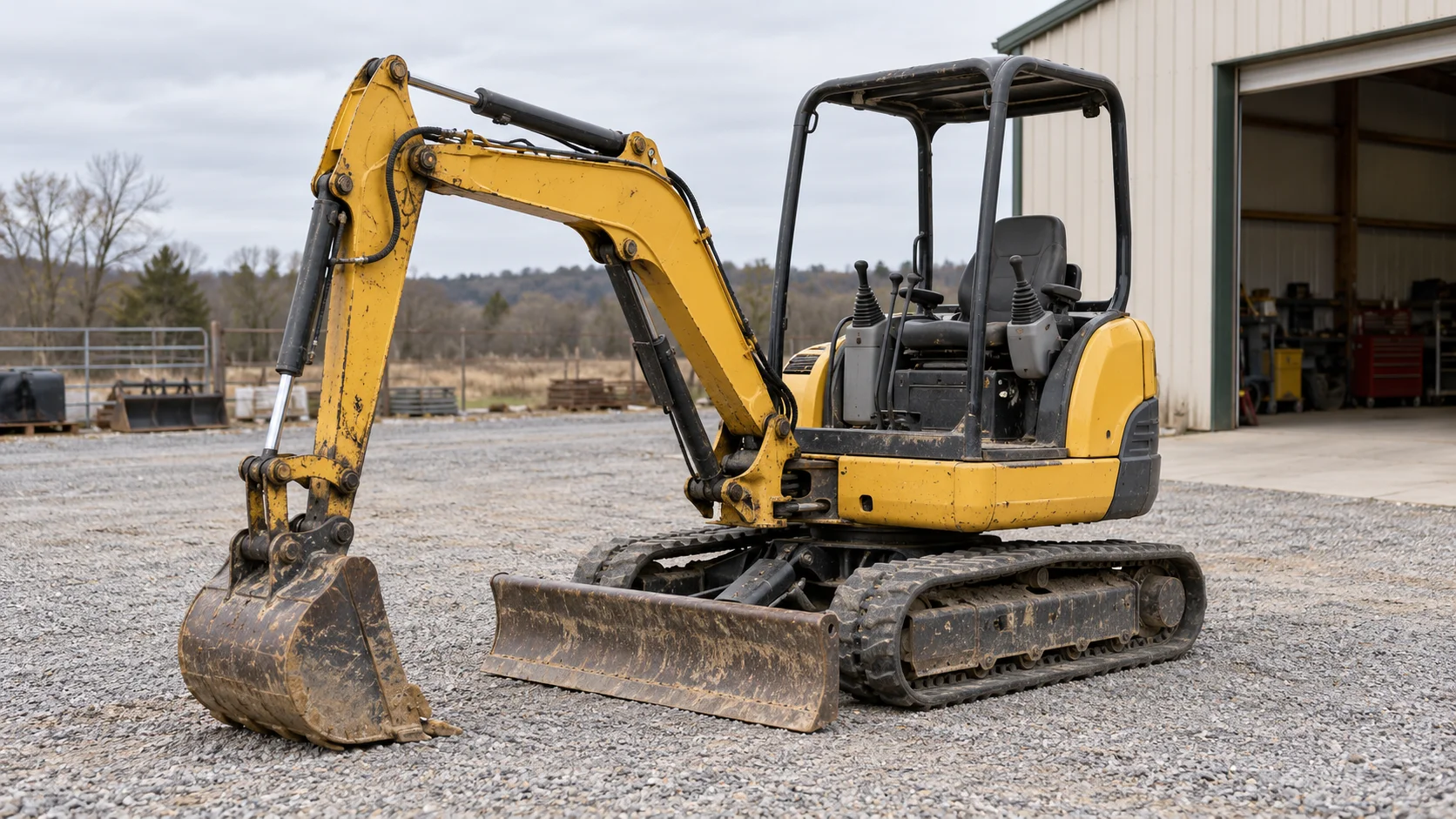
Ordering mini excavator parts from the model decal alone can leave you with a cylinder, bushing or track that does not match the installed assembly. Start with the machine model and serial number, then identify the blade arrangement, boom-offset pivot, track marking or drive assembly involved. For engine filters, add the engine's complete model and serial number.
For SANY mini excavator parts, work through these checks before agreeing a replacement:
- Blade: straight or angle arrangement, cylinder identity and mounting eyes.
- Boom swing: pivot location, bushing dimensions, pin and retention details.
- Undercarriage: full track code, inner profile and mating rollers, idlers and sprockets.
- Travel drive: installed assembly number, mounting geometry and hydraulic connections.
Use the SANY excavator parts catalog to browse parts, or go directly to the SY35U, SY50U or SY60C model page. The checks below help turn that model-based search into an assembly-specific request.
Separate boom offset, tail clearance and blade configuration
Record these as separate features. The boom-offset pivot lets the digging equipment move sideways relative to the upperstructure. Tail clearance describes the rear of the upperstructure as it rotates. The blade has its own linkage, cylinders and controls. A description such as “zero-tail mini” leaves all three parts identities unresolved.
SANY America's SY35U product specification lists a swing boom, true zero-tail swing and a 4-way angle blade. Its Boom Swing Family brochure distinguishes zero-tail SY35U and SY50U configurations from the conventional-tail SY60C. Use the documentation matching your machine's market and serial number, then photograph the equipment actually fitted.
A useful overview photo shows the front boom pivot, the blade and the track frame. Add the machine identification plate as a separate close-up. This keeps a request for the boom swing bracket distinct from a request for the upperstructure swing bearing, swing motor or center swivel joint.
Dozer blade parts: identify the cylinder and its mounting
For a blade cylinder or pin request, capture the blade arrangement first, then the connection details. A straight blade and an angle blade can involve different assemblies. Record whether the machine has a blade float function, and identify whether the requested cylinder lifts the blade or changes its angle.
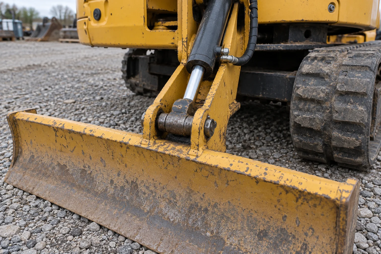
Include the cylinder eye, both mounting ears and the pin retention arrangement in a blade-parts photo set.
Send the cylinder's readable assembly number, a view of the complete cylinder, both mounting ends and accessible hose connections. For a pin or bushing, record the corresponding dimensions in the worksheet below. For a seal kit, match the cylinder assembly and its parts breakdown; “blade cylinder” alone leaves the kit identity incomplete.
Blade float describes an operating function. Identify rod seals, piston seals, pivot seals and other service items by their position in the correct assembly drawing. This avoids confusing a blade float feature with a floating face-seal description used for another component.
If the blade sinks or the machine travels unevenly, include the operating conditions and the technician's findings with the request. Selecting a center swivel joint requires the installed joint reference and the matching hydraulic schematic. Have the technician establish the relevant port functions and carry out the prescribed diagnostic checks before choosing a replacement. Keep hoses connected for identification photos; hydraulic pressure checks belong to the machine's service procedure.
Boom swing bracket: record the three bushing dimensions
The three basic bushing identification fields are inside diameter, outside diameter and axial width. Match them with the pin, housing and retention details before selecting a replacement. SKF's Bushings, thrust washers and strips catalog distinguishes shaft, housing, bushing and width dimensions; those relationships provide a useful way to organize a pivot request.
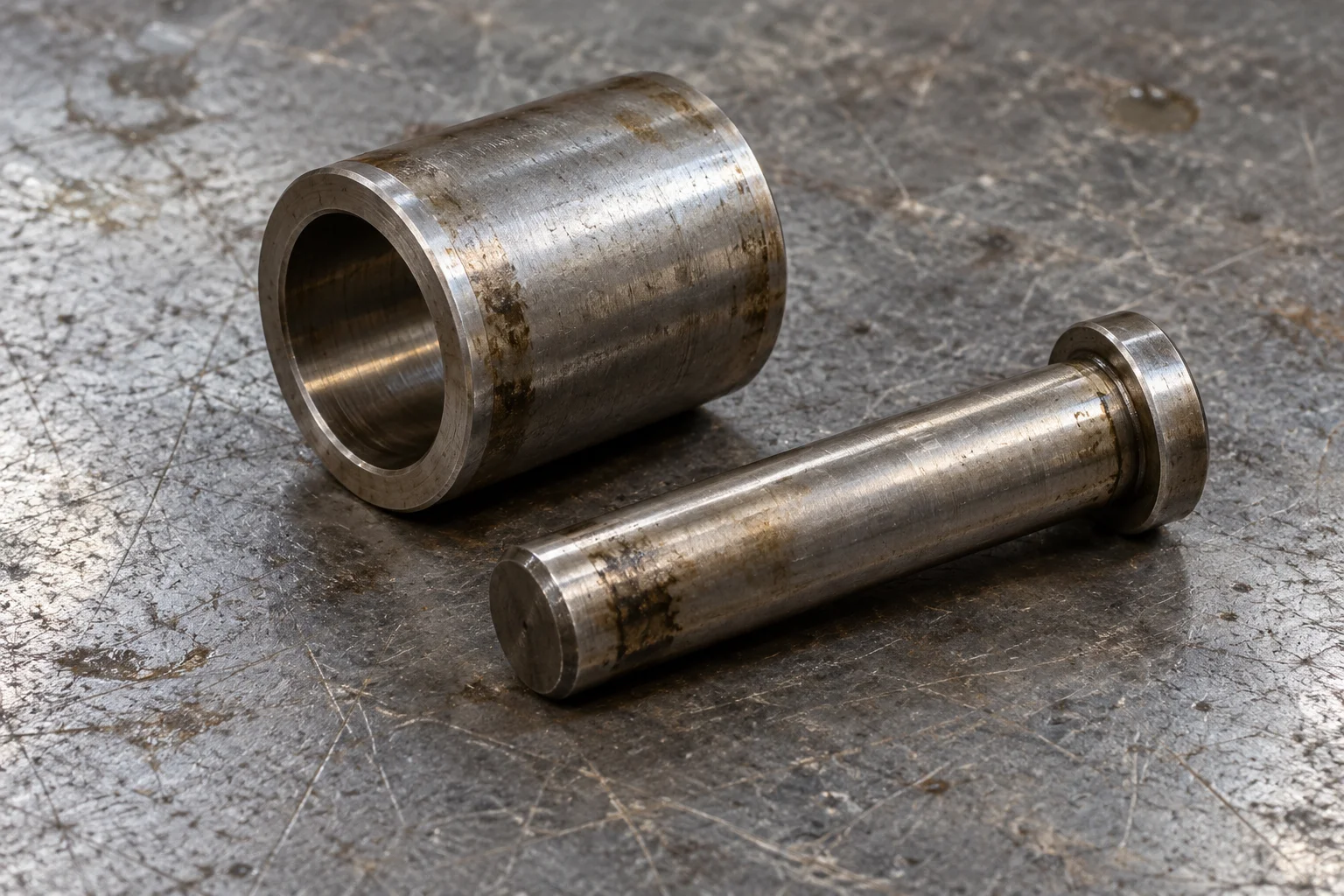
The bushing bore, outer surface and axial width correspond to different fit checks; record the mating pin separately.
Use this worksheet for the boom-offset pivot or a blade-cylinder eye. Name the exact joint in each request so dimensions from different positions stay together.
| Field to record | Matching detail | What to send | | ---------------------------------- | ---------------------------------------- | --------------------------------------------------------------------------------------------- | | Bushing inside diameter (ID) | Mating pin diameter | Measured bore and pin readings, in mm, with the drawing's nominal sizes separately identified | | Bushing outside diameter (OD) | Housing or mounting-eye bore | Bushing OD and housing measurement from the technician | | Bushing axial width | Available seat length and adjacent parts | Width, installed position and any flanges, seals or spacers | | Pin diameter and working length | Full supported length through the joint | Dimensioned sketch, pin-end views and retention details | | Housing and mounting ears | Joint arrangement | Ear spacing, bore locations and photographs of the complete connection | | Lubrication and retention features | Grease passages and locating hardware | Grease-hole layout, grooves, retainers and readable part references |
A worn bore reading describes the condition of the removed part. Confirm the replacement's nominal dimensions and fit against the applicable drawing. Also identify the specified bushing material and seal arrangement through the parts information; color and appearance alone are poor ordering references.
Let a qualified technician collect disassembled measurements under the machine's safe service procedure. For an assembled machine, begin with accessible photos and assembly numbers. Excessive movement should lead to a joint inspection covering the pin, bushing, housing and retention hardware before deciding which items to replace.
Rubber tracks: read the complete marking and check the mating parts
A rubber-track request needs the manufacturer's full marking, its decoded dimensions and the inner profile. Preserve the order of the characters in the photo. Different notation layouts can place link count and pitch in different positions, so write the field names beside the decoded values.
Bridgestone's New Generation Features — Rubber Tracks for Excavators, page 11, gives the notation example 300 × 84 × 52.5 F S. In that example, 300 is width in millimeters, 84 is the number of links, 52.5 is pitch in millimeters, F is the tread-pattern code and S identifies the embedded-metal type. Use this to understand the fields, then decode your installed track's own marking with its manufacturer information.
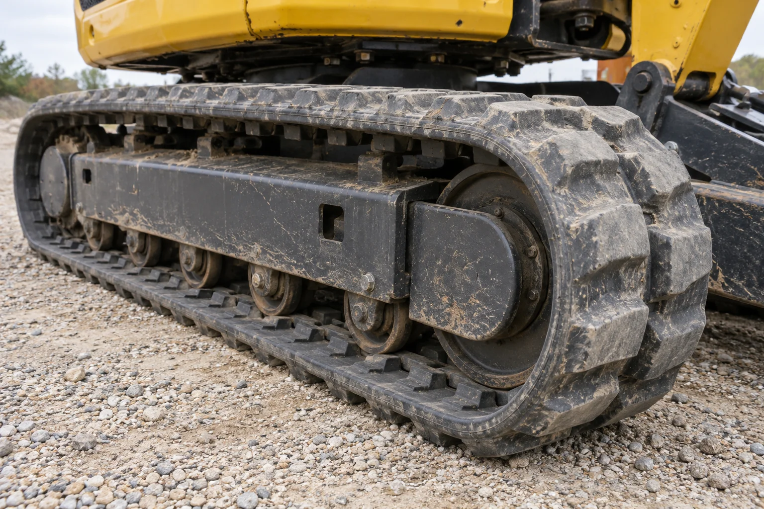
Photograph the inner guide profile and roller contact path alongside the outer tread and complete molded marking.
SANY America's SY35U specification lists a standard 300 mm belted rubber track, four track rollers per side and one carrier roller per side. To turn a width specification into a replacement-track request, add the pitch, link count and compatible inner profile for the installed assembly.
Inspect the sprockets, rollers and idlers with the track. Bridgestone's care guidance identifies worn or damaged undercarriage components as factors affecting track performance and directs owners to the vehicle operating manual for tension requirements. Include visible wear or damage in the photo set so it can be assessed before a new belt is fitted.
For a change of track material, use the rubber-versus-steel track compatibility guide to check the undercarriage and jobsite requirements.
Travel motor and final drive: confirm mounting and hydraulic functions
Compare a proposed drive against the installed assembly number, mounting drawing and port information. SANY America's SY35U specification lists an axial-piston travel motor with a parking brake and two travel speeds. The replacement check therefore needs to cover hydraulic functions as well as physical installation.
Ask for confirmation of these interfaces:
- Assembly identity: complete drive and motor references, including suffixes; confirm whether the quote covers the motor, reduction gearbox or complete assembly.
- Machine mounting: locating diameter, bolt count, bolt spacing or pitch-circle diameter, and mounting thread specification.
- Sprocket connection: mounting pattern and the dimensions shown on the relevant drawing.
- Hydraulic ports: labels, locations, thread designations and sealing geometry, supported by a documented port map.
- Operating functions: confirmation of the required travel-speed, brake and drain connections against the machine schematic and replacement documentation.
A thread designation and a sealing form describe different details. For example, ORFS identifies an O-ring face-seal connection; the connection still needs its thread and size specified. Obtain square-on port and mounting-face photos when safely accessible, or use photographs of an already removed unit. Keep the hoses and fittings identified by position rather than guessing their function from size.
Before accepting a replacement, resolve any mismatch between the installed identifiers and the proposed drawing. A shared model name is a useful search starting point; the assembly and interface match is the purchasing decision.
Engine filters: include the full engine plate
Send the engine model, complete suffix and serial number with the excavator plate and existing filter reference. YANMAR's Genuine Parts FAQs requires both the complete model number and serial number to identify an engine or product.
The detail matters: SANY's SY35U Stage III product page lists a Yanmar 3TNV88, while SANY America's SY35U specification lists 3TNV88F. Copy the full string from your engine plate and match the applicable engine parts listing. Include a photograph of the old filter label and its installation position to keep oil, fuel and other filter requests clearly separated.
Send an assembly-specific parts request
Start with the machine plate, required quantity and the component's location. Then attach the relevant information from the checks above:
- Blade or boom pivot: overview and close-up photos, assembly references, cylinder identity where relevant, and the completed pin/bushing dimensions.
- Track or undercarriage: complete molded track code, decoded fields, inner-profile photos and the mating components being requested.
- Travel drive: drive/motor references, mounting details, port photos and replacement-drawing questions.
- Engine filter: full engine model and serial, old filter reference and installation view.
Keep observed symptoms and confirmed measurements in separate lines. That gives the parts request a clear starting point for checking assembly identity and fitment. Send the photos and details through WhatsApp, or continue with the parts catalog. Find more identification and maintenance guides in SANY parts news and guides.
Last reviewed: Oct 27, 2026