

Low oil or the wrong refill level can turn a SANY final-drive service into a gearbox repair. Base the final drive oil change on the machine's matching maintenance manual, then inspect the drained oil and locate any seal leakage before ordering parts.

Interval, oil level and leak path are separate checks. Conceptual hardware view; use your drive's manual for its plug layout.
Use the specified oil, service interval and level datum for the exact SANY machine and fitted drive. The SY215C LC/SY225C LC December 2019 manual provides an annual or 2,000-hour change example, but that schedule does not establish the interval for every excavator. A falling level with an external leak and a gearbox level that repeatedly rises need different investigations. This guide connects the service record, oil observations and sealing boundaries so you can prepare a repair request with evidence.
Start with the SANY final-drive parts hub for assembly sourcing. If the requested part boundary is unclear, use the final drive versus travel motor guide before comparing a gearbox-only quote with a complete travel unit.
Find the oil-change interval for the fitted drive
Use the hour and calendar triggers in the matching operation and maintenance manual. Record the initial service requirement separately from the repeating interval; neither the machine's size nor a generic supplier chart establishes it.
Swipe or scroll horizontally to view the full table.
| Input or item | Value or source | Why it matters |
|---|---|---|
| Machine and fitted drive | Machine PIN/serial, drive tag, manual revision | A replacement drive may require its own service instructions. |
| First and repeating changes | Matching manual and completed service log | Distinguishes break-in service from recurring work. |
| Oil specification | Lubricant table, ambient range and product data sheet | Viscosity alone does not establish suitability. |
| Level reference | Manual's orientation, temperature and fill datum | Makes before/after readings comparable. |
For a scoped example, SANY manual SSY004846200, revision 1219, lists final-drive level checks weekly or at 50 hours, oil sampling at three months or 500 hours, and replacement annually or at 2,000 hours (pages 5-17 and 5-19). Keep the calendar limit as well as the meter limit. Match any later service instruction to the serial number before applying this baseline.
For planning, remaining hours = last-change meter + specified interval − current meter. With hypothetical log inputs of 4,000 hours at the last change, a confirmed 2,000-hour interval and a current reading of 5,850 hours: 4,000 + 2,000 − 5,850 = 150 hours remaining. If the calendar limit arrives earlier, use that date. Leakage, contamination or abnormal operation needs assessment without waiting for the scheduled change.
Choose excavator final-drive oil from the specification
Choose the lubricant by the complete manual requirement and operating-temperature range. Do not select 85W-90 or 80W-140 merely because the label says gear oil, or substitute thicker oil to conceal leakage.
SAE J306, revised February 2025, classifies lubricant viscosity; its public scope excludes other lubricant characteristics. A viscosity grade therefore does not establish additive performance, seal compatibility, OEM approval or a drain interval. ISO viscosity grades and SAE grades also use different classification systems; a numeral from one is not a conversion into the other.
The cited SANY manual's industrial gear-oil table identifies EP oil, API GL4 or GL5, and an ISO 3448 grade 220/AGMA reference (page 5-12). Use that as a document-specific reference, then confirm the actual fitted drive's lubricant instruction and the candidate oil's data sheet. An oil already in the hub with an unknown identity is a service-history gap to resolve, rather than a basis for mixing products.
Inspect the level datum and retain the drain evidence
A level opening is a reference point; its lower edge is not automatically the required oil surface. In the cited SY215C LC/SY225C LC manual, the drain sits at the bottom and the level mark is horizontal. The check allows the level within 10 mm below the opening's bottom, while the refill instruction specifies 10 mm below it (pages 5-53–54).
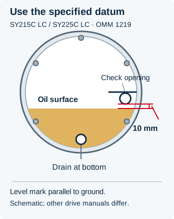
The 10 mm refill offset belongs to manual revision 1219 for these models. Other plug layouts and manuals can specify a different datum.
Decision rule: if the measured level falls outside the matching manual's permitted band under its prescribed setup, resolve the level or leakage condition before treating the drive as ready for work. Do not transfer the 10 mm example to an unidentified unit.
Have a qualified technician follow the complete service procedure, including cooling, machine isolation, PPE and controlled release of residual pressure. The cited manual warns about hot oil and pressure; a stationary machine does not establish that a plug is safe to remove.
Keep a separate record for each side:
- Photograph the cover orientation, the measured level and the first wet area before cleaning obscures the path. Label the side and meter reading.
- Record the drained volume and refill amount as observations. Residual oil, tilt and previous top-ups can change these numbers; they do not replace the specified level check.
- Where a magnetic plug is fitted, photograph debris before wiping it. Preserve visible flakes, chips or unusual deposits for assessment. A magnet will not collect every wear material, and a clean magnet cannot clear the whole gearbox.
- Retain a labelled oil sample if contamination or wear is suspected. Record the oil product, time since change and sampling conditions; colour alone does not identify water, viscosity or a failed component.
Ask the service technician to assess visible fragments, water contamination, new noise or roughness before returning the machine to work. Do not create a universal acceptable quantity of metal paste from a photograph.
Separate floating-seal leakage from internal oil transfer
Locate the first wet point and compare repeat level readings made under the same setup. The floating face seal protects the rotating hub's external boundary. Internal shaft sealing separates the motor and gearbox fluid spaces in applicable assemblies; verify the actual arrangement on the drive drawing.
Trelleborg's mechanical face-seal description shows opposed metal rings with lapped faces and elastomer supports, with one ring stationary and the other rotating. That explains why the external seal is a different repair boundary from the motor shaft seal. It does not identify a SANY replacement seal by appearance.
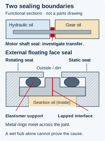
Two sealing boundaries, two investigations. This functional schematic does not specify the construction or seal dimensions of a particular drive.
A rising gearbox oil level changes the repair question. First exclude an incorrect refill, a changed cover orientation and inconsistent checking conditions. If the rise repeats, ask the technician to investigate possible motor-to-gearbox transfer and its cause. Repeatedly draining the excess or changing the external floating seal alone does not resolve an internal transfer path.
Swipe or scroll horizontally to view the full table.
| Observation | Boundary to investigate | Evidence for the technician | Dominant Failure Mode & Prevention |
|---|---|---|---|
| Wetness starts at a service plug | Plug seal, seating surface or thread | Clean-area photograph, correct seal and tightening instruction | Local oil loss; use the specified plug seal and inspect damaged seating surfaces. |
Oil emerges at the rotating hub/frame-side gap | Floating face seal and adjacent housing/bearing condition | First wet point, level trend, debris history and technician's bearing inspection | Oil loss or dirt ingress; confirm seal fit and the condition of its supporting components. |
Gearbox level repeatedly rises after a correct refill | Possible internal motor-to-gearbox transfer | Comparable level readings, oil sample and drive-specific motor/case-drain assessment | Fluid mixing or overfilling; diagnose the transfer path and motor-side cause before resealing. |
Metal fragments, roughness or recurring contamination | Gear train, bearings and contamination source | Retained debris/sample and inspection findings | Continued wear after a partial repair; establish the damage extent and cleaning/repair scope. |
These are investigation routes, not diagnoses from symptoms alone. Use the drive maker's limits for bearing condition, case pressure and hydraulic testing. Do not run a stalled-track test or restrict a drain line based on a generic online threshold.
Compare the repair scope over the same period
A seal-only request makes sense after inspection establishes that the seal, its running surfaces and supporting components can be serviced. Gear or bearing damage changes the quotation scope. Ask whether the proposal covers the external seal, motor seals, gearbox, or complete travel unit, and what inspection or cleaning work is included.
Use the seal-kit category for the related sourcing path, but confirm the kit contents against the drive tag. A generic motor seal kit is not proof that the floating face-seal pair is included.
For each quote, use the same planning period and duty assumptions:
Repair-period cost = parts + labour + oil/cleaning + freight/core costs + downtime hours × your downtime cost per hour + any separately estimated repeat work.
As a hypothetical time example, two planned service visits of three hours each plus one return visit of four hours total 2 × 3 + 4 = 10 hours. At your entered downtime rate D, the downtime entry is 10D. This is worksheet arithmetic, not a prediction that a particular repair will require those visits. Count each cost once; use actual quotations and your fleet records for the remaining entries.
Compare a planned oil service with another planned oil service, or alternative repairs for the same inspected damage. Comparing an oil-change price with a complete assembly price hides the difference in work covered.
What to send us for a fitment and quote request
Send the identifiers together with the observations that changed the repair decision. We use the machine and component details to check compatibility before quoting; a photo of oil colour alone cannot identify the required kit.
Swipe or scroll horizontally to view the full table.
| Item | Why we need it | Example format |
|---|---|---|
| Machine model/PIN and drive tag | Match the machine and installed assembly | Readable plate photos and full tag suffix |
| Oil and service history | Understand the recorded service condition | Product label, manual revision, last-change date and hours |
| Leak location and level trend | Describe the boundary needing inspection | Left/right photos, checking setup and dated readings |
| Debris and inspection findings | Define seal-only, gearbox or assembly request | Plug/sample photos and technician's findings |
| Quantity and destination | Prepare quotation and shipping options | Units required and destination country/port |
Send this record and your photos through the WhatsApp compatibility desk below to request the correctly identified parts and quote. Keep the workshop diagnosis with the service technician; confirm the replacement scope before ordering.
Method and sources
Updated October 19, 2026. The service example uses the SANY SY215C LC/SY225C LC Operation and Maintenance Manual, part SSY004846200, revision December 2019, pages 5-12, 5-17, 5-19 and 5-53–54. Match the current manual and any replacement-drive instructions to your machine before servicing.
The viscosity distinction follows SAE J306's February 2025 public scope. The floating-seal explanation uses the seal manufacturer's Mechanical Face Seals catalogue, April 2026, general description. Sources were retrieved October 19, 2026. The diagrams explain service datums and functional boundaries; the worksheet uses explicitly hypothetical inputs. No universal seal dimensions, hydraulic test limits or lubricant substitutions are established here.
Last reviewed: Oct 19, 2026