

A loose track can cause downtime, while an over-tight track loads the undercarriage unnecessarily. For SANY excavator track tension, first measure sag using the machine's matching manual, then distinguish a grease-valve fault from an adjuster-cylinder problem before ordering seals.
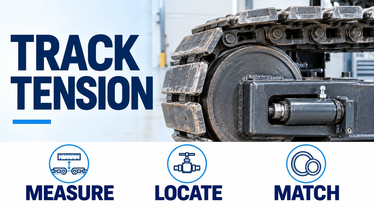
Track tension checks connect the sag measurement, grease valve and adjuster seal condition. Conceptual hardware view.
Excavator track adjustment starts with the correct measurement datum, track type and manual revision. Adding grease is appropriate only when that check calls for more tension and the adjustment system works normally. A track that repeatedly goes slack needs a recorded leak-location and component check. This guide gives a model-scoped measurement example, a symptom table and a workshop handover checklist so you can distinguish adjustment, valve service, cylinder resealing and assembly replacement.
For related component groups, start with the SANY undercarriage parts hub. Track-material selection belongs in the rubber versus steel track guide; the measurements below must match the configuration already fitted.
Record the machine and measurement method first
A sag reading is useful only when its measurement points and machine setup are recorded together. A lower-run clearance on a raised compact excavator and two upper-run gaps on a larger crawler are different measurements. Do not transfer a number between them.
Swipe or scroll horizontally to view the full table.
| Input or item | Value or source | Why it matters |
|---|---|---|
| Model and serial | Complete machine nameplate | Select the manual and parts record for this unit. |
| Track construction | Fitted rubber belt or steel chain/shoes | Use its prescribed setup and sag datum. |
| Reference condition | Matching operation and maintenance manual | Defines cleaning, positioning and settling movement. |
| Sag and leak location | Measurements in mm and photos from a safe position | Separates an adjustment need from a recurring fault. |
Use the maintenance preparation in that manual. For example, the SANY SY215C LC/SY225C LC operation and maintenance manual, revision 1219, specifies a hard, level surface, lowered work equipment, blocked tracks and the applicable lockout/tagout procedure before maintenance (p. 2-8). Any prescribed travel or lifting check needs its own controlled procedure and clear work area. Do not improvise a raised-track setup from a photograph.
Measure the sag against the matching manual
The SY215C LC/SY225C LC manual, revision 1219, pp. 5-96–5-97, provides a useful example of why the datum matters: it adds two upper-run gaps. Its reference preparation includes cleaning the track, rollers and frame, driving forward two machine-lengths on flat, stable ground, then parking and preparing for service.
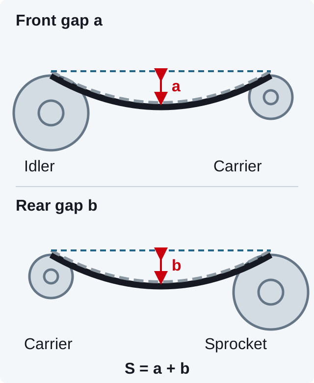
Schematic, not to scale. Each gap ends at the top of the shoe. Add the gaps only when the matching manual uses this two-gap method.
For this method, measure the front span between the forward carrier roller and idler, and the rear span between the rear carrier roller and sprocket. A taut string or straightedge provides each reference line; measure down to the top of the track shoe at the positions shown in the manual.
Total sag S = front gap a + rear gap b, with all three values in millimetres. The specified total for this manual is 76.2–101.6 mm (3–4 in). That is the sum, not the allowance at each location.
Worked example with hypothetical readings: S = 45 mm + 40 mm = 85 mm. That total falls inside this manual's band only if the machine configuration, preparation and measurement points match. It does not establish a setting for a different SANY model or manual revision.
Rules of thumb for the 1219 two-gap method: if S is below 76.2 mm, the measured track is tighter than that specified band; if S is above 101.6 mm, it is looser. Confirm the setup before adjustment. If the matching manual specifies another method, use its limits instead.
Copy this record for each side of the machine:
Swipe or scroll horizontally to view the full table.
| Record field | Your entry |
|---|---|
| Model, serial, track type, side | ________________ |
Manual revision, page, setup and allowed band | ________________ |
Gap a / gap b / sum, or other prescribed datum (mm) | ________________ |
Before and after prescribed adjustment/recheck | ________________ |
Leak location, debris and visible damage | ________________ |
Separate the grease fitting, release valve and cylinder
The grease fitting admits grease; the release valve provides the prescribed pressure-release path. In the 1219 manual, figure 5-153 identifies them separately. Its warning specifically says not to loosen the fill fitting when reducing tension. High-pressure grease can injure you, so use the required PPE, tools and off-axis working position described in the matching manual.
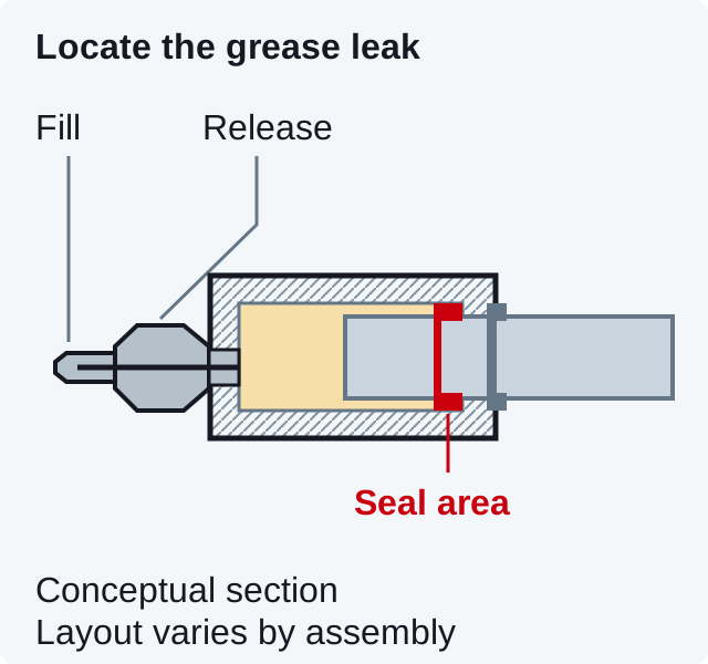
Conceptual integrated fitting/valve arrangement. Distinguish the fill point, release-valve body and cylinder seal area. The recoil spring is omitted; confirm the layout on your assembly.
When more tension is required, the matching manual describes adding grease through the fitting and rechecking after its specified movement. When less tension is required, follow its release-valve procedure. Valve opening limits, tightening torque and grease grade belong to the exact assembly instructions. A generic number of pumps or turns cannot establish correct sag.
Use the table as a diagnostic handover, not as proof that a particular component has failed. Inspect from outside the discharge path; do not use your hand to find a pressure leak.
Swipe or scroll horizontally to view the full table.
| Observed condition | Check before ordering | Dominant Failure Mode & Prevention |
|---|---|---|
Sag outside the band, without a recurring leak | Cleanliness, correct datum and manual-prescribed adjustment/recheck | Misadjustment from the wrong measurement; record the setup before changing tension. |
Fresh grease at the fitting or release-valve body after closure | Exact leak origin and valve identification, assessed by the technician | Loss through the valve path; resolve valve condition before assuming a cylinder kit will fix it. |
Recurring slack with grease at the cylinder/plunger boundary | Seal area and mating surfaces after authorized removal and pressure release | Sealing loss or damaged mating surfaces; inspect the hardware before fitting replacement seals. |
Track will not tighten or release normally | Stop and refer the assembly to qualified service using the correct manual | Unresolved pressure or mechanical fault; do not remove the fitting or dismantle the spring to force a result. |
Choose a seal kit or assembly after the workshop check
Order a seal kit only after the assembly identification and hardware inspection support resealing. A kit replaces specified sealing elements; it cannot restore a damaged cylinder surface, bent plunger, damaged thread or faulty recoil assembly. Ask the technician to compare those parts against the applicable service limits before approving a repair route.
Treat 60018972K as a reference to verify if it appears on your old kit, quotation or parts record. Confirm the adjuster assembly number and serial application before ordering; that code alone does not establish compatibility or the kit contents. The seal-kit category covers several different assemblies, so identify this request as a grease track-adjuster cylinder, rather than a boom cylinder or travel-motor repair.
The SANY SY16C preliminary service manual M207-0617, section 6.5.4, illustrates why cylinder seal work and spring work must be planned separately: it identifies a seal and dust ring, and describes a highly loaded spring assembly. Its instructions and settings apply to that assembly, not to every SANY adjuster. Releasing grease does not establish that a recoil spring is unloaded.
For a seal replacement job, agree these handover stages with the workshop:
- Confirm the serial-matched service instructions, assembly number, removal method and required support/restraint equipment before starting.
- Have the technician isolate the machine and establish the specified pressure-release and spring-restraint conditions. Stop if pressure cannot be released normally.
- After authorized removal, record the old seal arrangement and inspect the cylinder, plunger, grooves and valve parts against the service criteria. Decide whether resealing or hardware replacement is appropriate.
- Match the replacement kit to the parts drawing. Use its specified seal profiles, orientation, installation aids and lubricant; do not infer the arrangement from seal colour or a generic picture.
- Reassemble to the correct manual, restore guards and carry out its tension and leakage checks. Record the final sag using the same datum as the initial reading.
This is a job-planning sequence for qualified service. Spring compression, retention hardware, seal orientation and assembly torques require the exact service procedure. If the workshop lacks that procedure or the required equipment, arrange specialist service before dismantling the adjuster.
Compare the repair routes over the same job window
Compare the full return-to-work cost, including the risk of reopening a damaged assembly. A lower kit price can lose its advantage if the cylinder also needs replacement after disassembly.
Job cost = parts + labour + freight + stopped hours × your site cost per hour.
Hypothetical arithmetic, using an assumed site cost of 80 currency units/hour: 3 stopped hours × 80 units/hour = 240 units of downtime cost. These inputs illustrate the calculation; enter your own costs and workshop estimates for each repair route.
Swipe or scroll horizontally to view the full table.
| Cost to record | Keep the comparison consistent |
|---|---|
| Kit or replacement assembly | Use confirmed contents and supply category from each quote. |
| Removal, inspection and reassembly | Include workshop labour, required tooling and any second opening. |
| Freight and stopped-machine time | Use the same destination and the same start-to-return-to-work window. |
Review the adjacent rollers, idler and chain with the workshop when assessing recurring slack. Use the undercarriage component hub to keep related parts in the same request, rather than buying a seal kit as an automatic response to any loose track.
What to send us for an adjuster parts inquiry
Send the record below for a compatibility check and quotation. As described on our about page, we match requests using the model, serial number, part number and photos, then state the available supply category in the quote.
Swipe or scroll horizontally to view the full table.
| Item | Why we need it | Example format |
|---|---|---|
| Model, serial and track type | Identify the machine configuration. | Full nameplate and track side-view photos. |
| Assembly number and kit reference | Check the requested valve, kit or complete adjuster. | Marking photo or parts drawing; include 60018972K only if present in your record. |
| Sag record and leak location | Explain the fault and the checks already completed. | Manual page, before/after measurements in mm and a safe-distance photo. |
Workshop findings, quantity and destination | Define the parts scope and shipment request. | Inspection notes, required quantity and destination port. |
Method and sources
Published and updated 19 October 2026. The measurement example and grease-valve distinction come from the SANY SY215C LC/SY225C LC Operation and Maintenance Manual, revision 1219, pp. 2-8 and 5-96–5-98, retrieved on that date. The component and workshop boundary also references SANY SY16C preliminary Service Manual M207-0617, section 6.5.4, pp. 6-39–6-40. Confirm current instructions for your serial through SANY or an authorized service provider; these older editions establish the examples above, not universal settings.
The official public scope of ISO 20474-1:2017, checked 19 October 2026, covers general earth-moving machinery safety, including maintenance, alongside the applicable machine-family parts. It does not supply the sag value used here or establish certification of a replacement kit. The diagnostic table and request checklist organize those source distinctions for parts selection; the cost example uses explicitly hypothetical inputs.
Last reviewed: Oct 19, 2026