

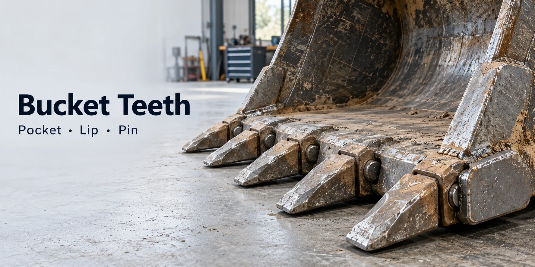
Start your excavator bucket teeth enquiry with the installed parts: record the tooth pocket, adapter nose, bucket lip and retention hardware separately.
For ESCO Ultralok adapter selection, record the lip thickness and ramp angle.
Do not infer the lip dimensions from the machine when selecting an Ultralok adapter.
Use the checks below to build a measurement record for replacement bucket teeth, adapters and pins. Keep the original drawing beside each set of measurements.
- Pocket: record the opening and depth against the tooth drawing.
- Nose: record the system identity and its wear-gauge results.
- Lip: record thickness, ramp profile and mounting details.
- Retention: photograph the pin and retainer separately.
For more parts-identification articles, visit our news and guides.
Begin with the bucket lip, not just the excavator model
In Ultralok adapter selection, the lip may be custom-sized or may have been replaced with a size different from the factory original.
Use the lip dimensions to determine which Ultralok adapters fit.
For Ultralok bolt-on adapters, measure the hole spacing accurately on the lip.
Ask for a clear side view of the lip and adapter, together with any surviving tooth, adapter and bucket markings. Include the excavator identification in the enquiry, and attach the measurements as a separate record.
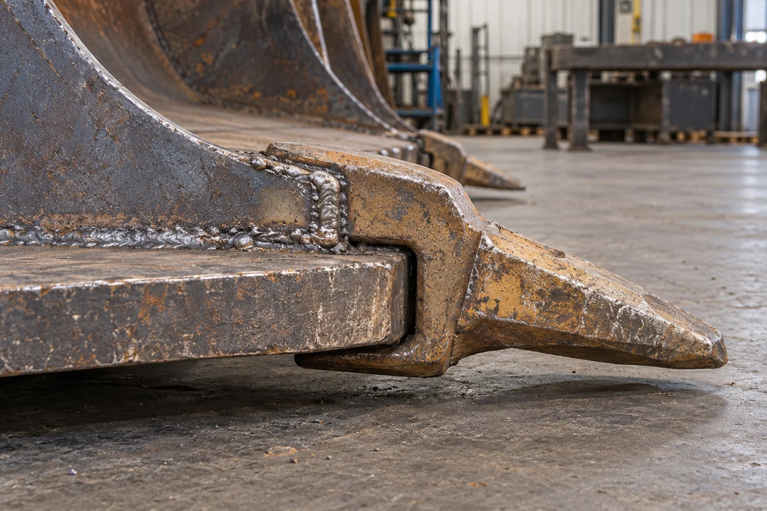
Capture a side view of the lip and adapter for the measurement record.
Lip-thickness catalogue examples
Keep each adapter part number beside its lip-thickness entry when comparing the adapters below.
-
ESCO Ultralok 3858BW-U60 has a listed lip thickness of 70 mm.
-
ESCO Ultralok 5865W-U60 has a listed lip thickness of 75 mm.
-
ESCO Ultralok 5898AW-U60 has a listed lip thickness of 80 mm.
-
ESCO Ultralok 6805AW-U60 has a listed lip thickness of 90 mm.
The ESCO Ultralok 3858BW-U60 ramp angle is 30 deg.
Keep the installation-gap check separate
For MTG weld-on straddle adapters, the gap between the upper adapter leg and the lip must be no greater than 4mm.
Label this entry “adapter-to-lip installation gap” on your record. Put the tooth-pocket measurements and nose-gauge results under their own headings.
Measure the tooth pocket against its own drawing
Record the drawing identity before transferring dimension letters to your worksheet. Photograph the pocket opening and mark the measurement endpoints on a copy of that photograph.
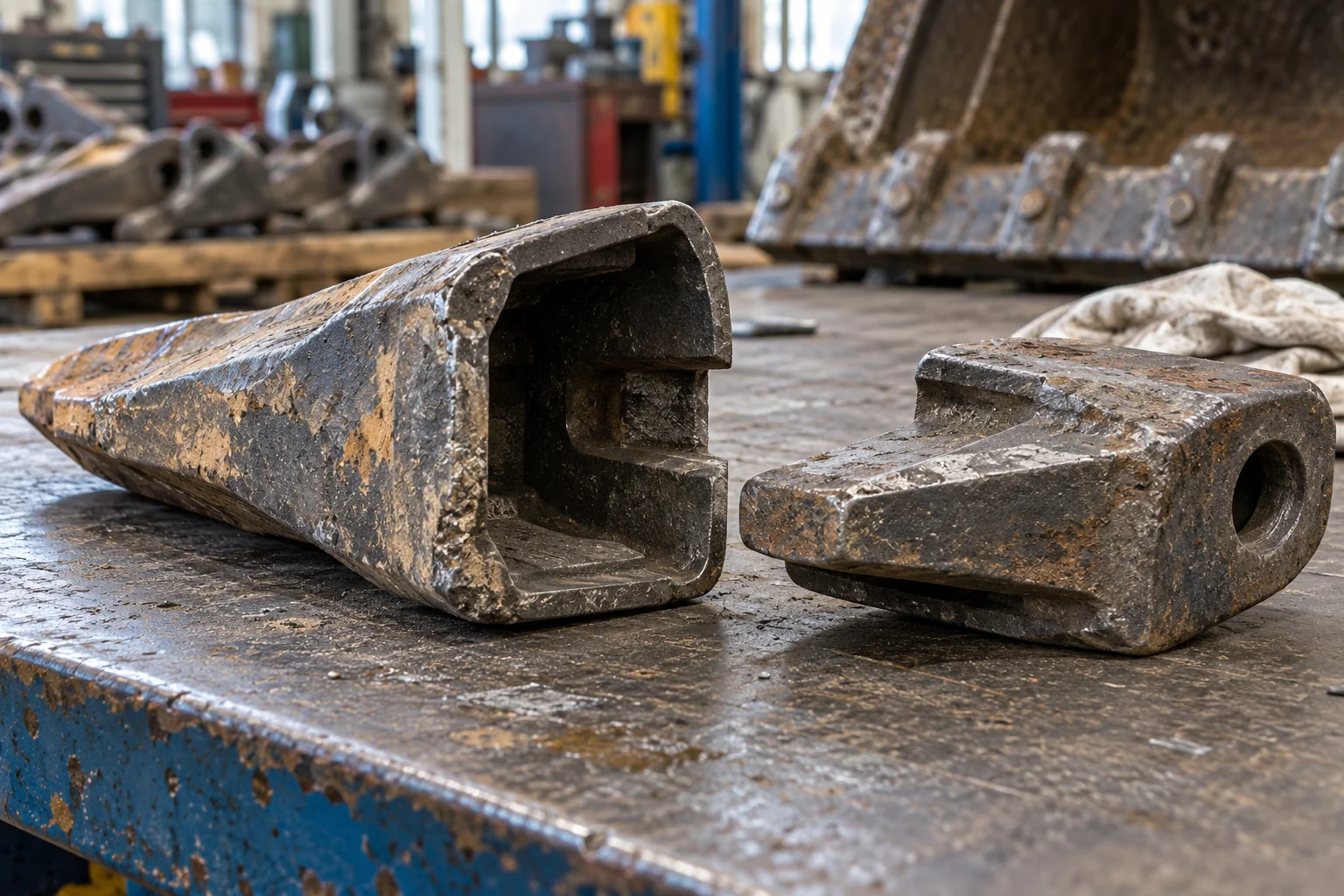
Photograph the pocket opening and the exposed nose as separate views.
For the Hensley XS04 tooth, pocket dimension C is 42 mm.
For the Hensley XS04 tooth, pocket dimension D is 45 mm.
Use the pocket diagram for those entries. Keep the pin drawing on a separate sheet when recording its dimension letters.
In John Deere’s Caterpillar replacement-teeth section, the extended adapter nosepiece and oversized pocket provide a nose fit between the tooth and adapter that yields strong impact resistance but a loose fit in the ramps.
Record where movement is observed, then use the identified system’s inspection method. Avoid writing only “loose tooth” in the measurement notes.
Check adapter nose wear with the specified gauges
For Hensley XS/Kmax nose evaluation, clean the nose exterior and pin hole before measurement.
Hensley XS/Kmax nose evaluation uses a horizontal nose gauge, a vertical nose gauge and a ruler to determine the extent of nose wear.
Record the gauge identity, contact position and observed gap alongside the applicable limit.
-
The Hensley XS40 maximum horizontal nose-gauge gap is 1.6 mm at the specified template locations.
-
The Hensley XS40 maximum vertical nose-gauge gap is 1.6 mm at the specified template locations.
-
The Hensley XS50 maximum horizontal nose-gauge gap is 2.4 mm at the specified template locations.
-
The Hensley XS50 maximum vertical nose-gauge gap is 2.4 mm at the specified template locations.
Enter these results under “nose-gauge gap”; reserve “pocket dimensions” for the tooth drawing measurements.
Hensley does not recommend rebuilding XS or Kmax adapter noses.
Inspect the surrounding bucket edge
Include the following Caterpillar walk-around checks with the adapter assessment:
-
Inspect the welds around the adapters and the bucket base edge for cracks.
-
Inspect scalloping wear between the bucket teeth and whether it extends to the adapters and their welds.
-
Inspect the base-edge ends for wear into the outer adapter and sidebar welds.
-
If sidecutters or protectors are fitted, inspect them for visible wear when assessing replacement.
Measure the lock pin and identify its retainer
For the LIS J350 lock-pin listing, technical identification requires checking the system size and the existing pin diameter and length.
Photograph both ends of the pin, its side profile and the separate retainer. Add an installed view showing the pin orientation. Write down the markings exactly as found.
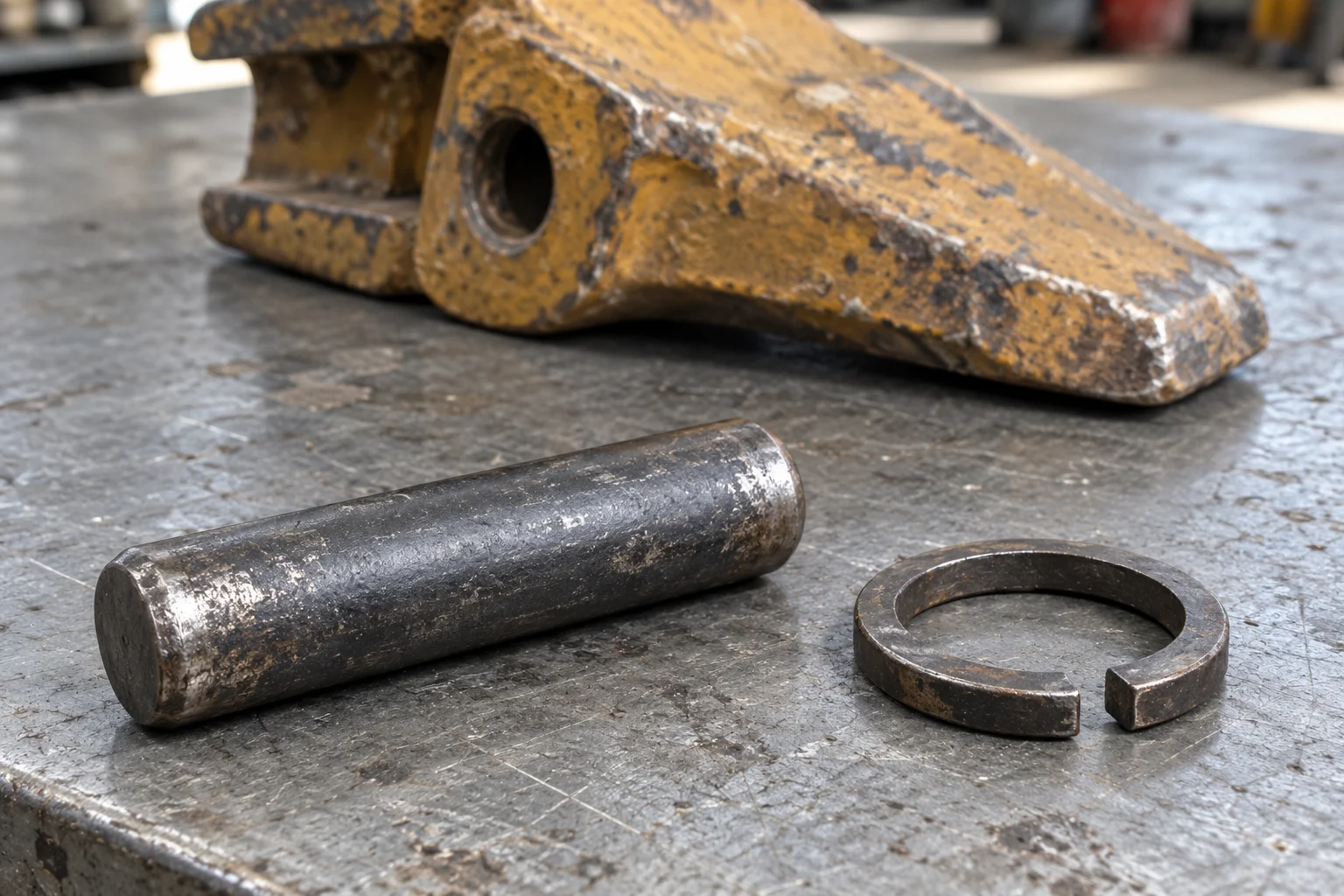
Include separate pin and retainer views with the enquiry.
John Deere original-line replacement teeth use a pin and split-washer retention design.
Pin-assembly drawing examples
-
The Hensley XS04P Standard Duty pin assembly dimension A is 57 mm.
-
The Hensley XS04P Standard Duty pin assembly dimension B is 11 mm.
-
The Hensley XS04P Standard Duty pin assembly dimension C is 23 mm.
Use the pin-assembly diagram to identify the endpoints for each letter, and attach your measured values beside the corresponding entries.
Record the retainer variant
For MTG STARMET polyurethane-retainer installation, the rigid polyurethane retainer must face out.
The MTG STARMET metallic-retainer installation procedure aligns the pin chamfer against the retainer edge.
Name the retainer variant in the enquiry and keep its installation instructions with the part record.
Prepare your bucket teeth enquiry record
Copy these prompts into your parts request and attach the photographs:
- Machine and bucket: identification, existing markings and full bucket view.
- Tooth pocket: drawing identity, opening width, opening height, depth and marked measurement endpoints.
- Adapter nose: markings, bare-nose views and system-specific gauge results.
- Bucket lip: measured thickness, ramp profile, mounting details and side-view photograph.
- Pin and retainer: markings, pin diameter, pin length, end views, retainer views and installed orientation.
- Condition: observations at the adapter welds, spaces between teeth, base-edge ends and sidecutters.
Use our part photography guide to prepare the images. Send the completed record with your bucket teeth enquiry, or browse excavator parts.
Send a bucket teeth enquirySources
- ESCO — Construction GET catalogue
- ESCO — Ultralok slim profile adapters with wear caps
- Hensley — G.E.T. Specification Manual
- John Deere — Construction Bucket Teeth
- MTG — WS Straddle Weld-on Adapter installation procedure
- MTG — STARMET Tooth System installation procedure
- Linser — LIS lock pin product data
- Caterpillar — GET Selection and Maintenance
Last reviewed: Oct 28, 2026